November 5, 2011
-
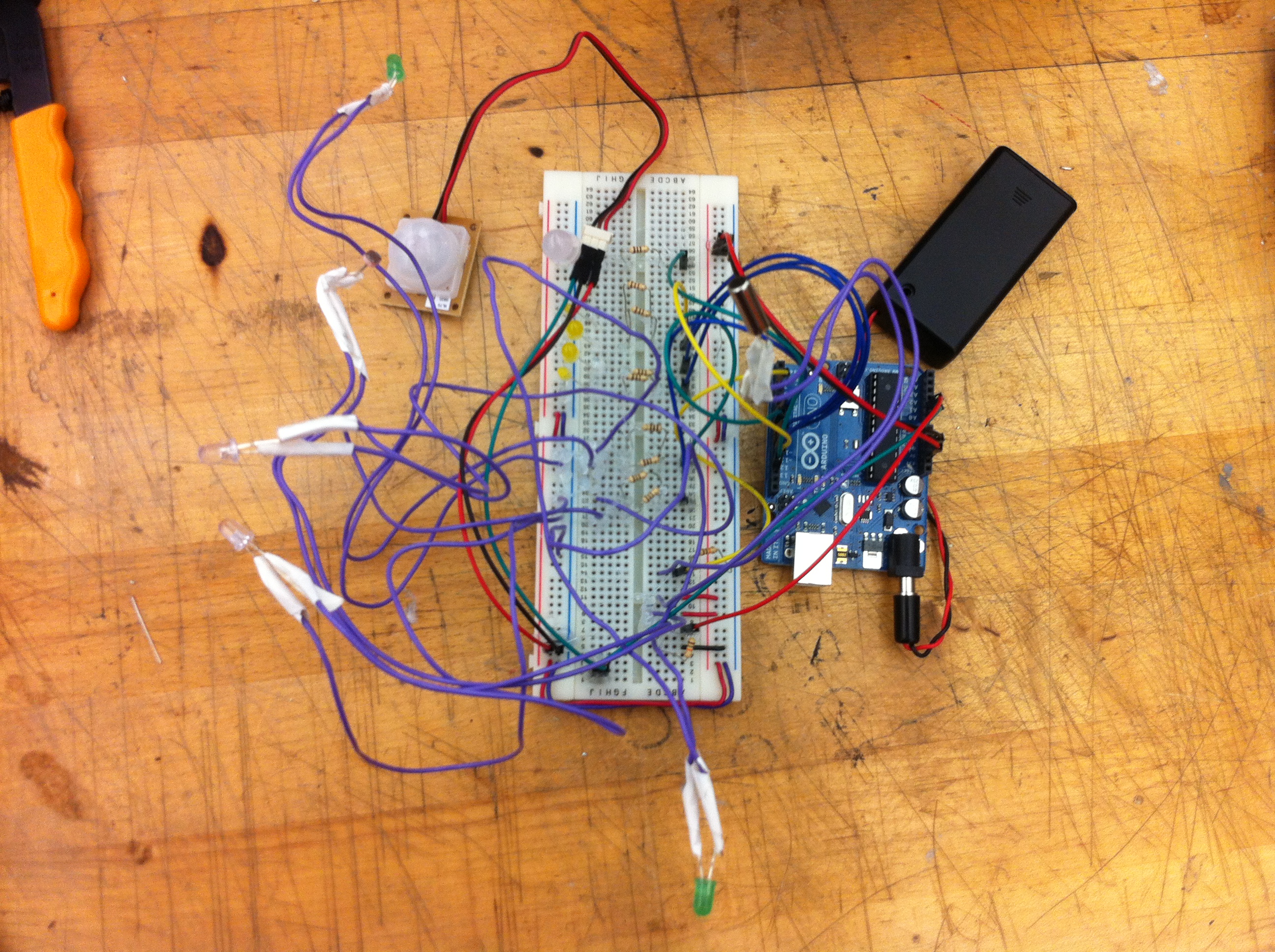
Meet the Hallowbot
1) Hallowbot 2) The basic idea of my Hallowbot is that communicates with a user. I…
-

Josef Ayala-Wake-O-Lantern!
Description: This pumpkin was a simple exercise in implementing a circuit inside of an enclosure. It’s…
-
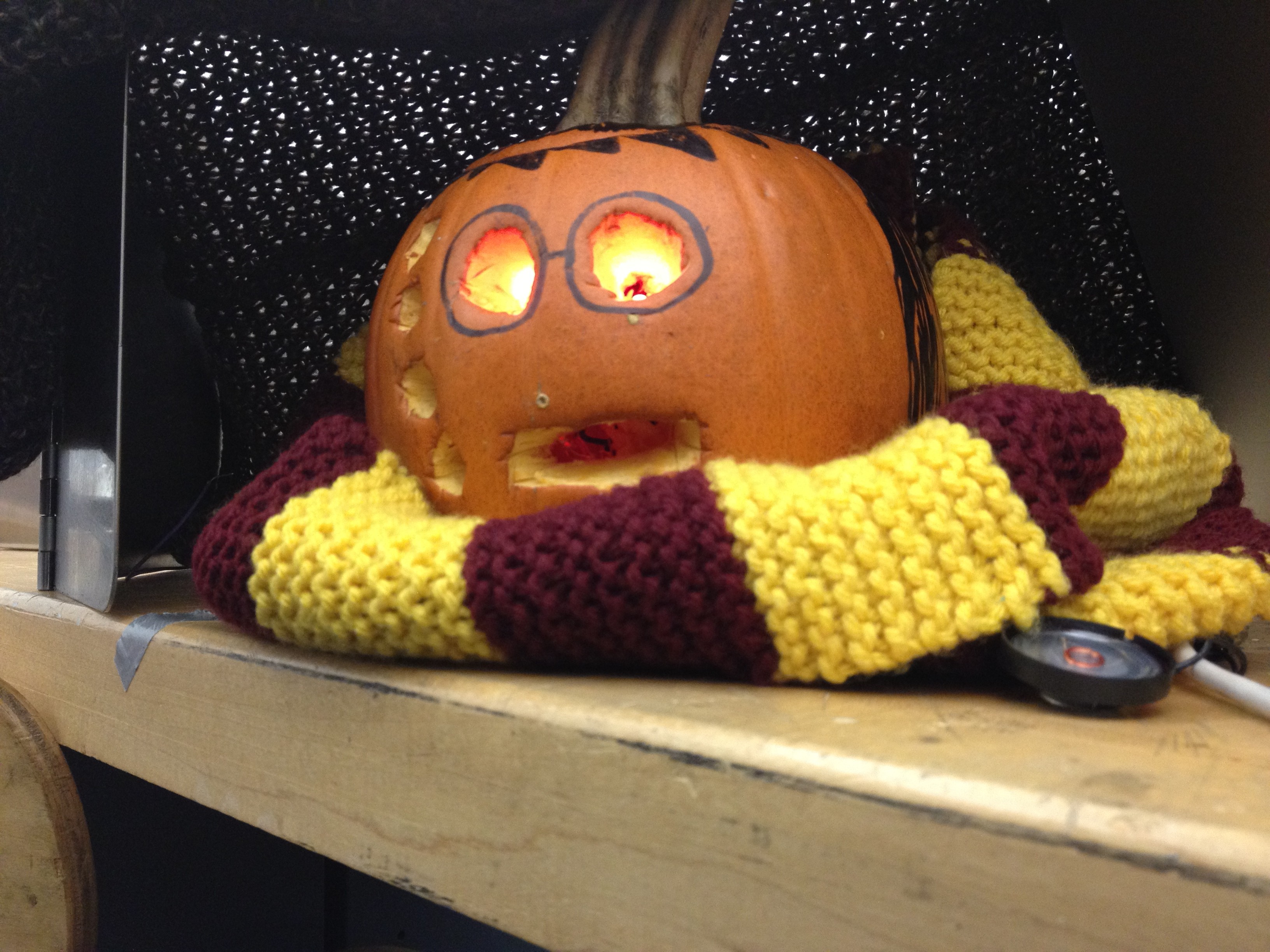
The Harry Potter Pumpkin
The Harry Potter Pumpkin is a social pumpkin that interacts with you based on proximity. From…
You must be logged in to post a comment.