Updates from October, 2012 Toggle Comment Threads | Keyboard Shortcuts

  • trytobegood 4:04 pm on October 12, 2012 Permalink | Reply  

    Game sounds 

    I’m still missing 2 sounds!

    Download my code


  • tiamtaheri 4:50 am on October 12, 2012 Permalink | Reply  

    sounds 

    Startup:

    Version 1:

    int speakerPin=8;

    void setup(){
    pinMode(8,OUTPUT);

    }
    void loop (){
    for( int y=0; y<3000; y+=2) {
    tone(speakerPin,random(10,y));
    delay(4);

    }

    }


    Version 2 (favorite):

    int speakerPin=8;

    void setup(){
    pinMode(8,OUTPUT);

    }
    void loop (){
    for( int y=0; y<3000; y+=2) {
    tone(speakerPin,random(0,y));
    delay(4);

    }

    }


    Version 3:


    int speakerPin=8;

    void setup(){
    pinMode(8,OUTPUT);

    }
    void loop (){
    for( int y=0; y<3000; y+=2) {
    tone(speakerPin,random(1000,y),6);
    }

    }


    You are wrong-sounds:

    Version 1:

    1. include “pitches.h”

    int melody [] = {NOTE_A1,NOTE_B0,NOTE_D2};
    int noteDurations [] = {1};

    void setup() {

    }

    void loop() {
    for (int thisNote = 0; thisNote < 3; thisNote++) {
    int noteDuration = 1000/noteDurations[thisNote];
    tone(8, melody[thisNote],noteDuration);
    int pauseBetweenNotes = noteDuration * 1.30;
    delay(pauseBetweenNotes);
    noTone(8);
    }

    }


    Version 2:

    1. include “pitches.h”

    int melody [] = {NOTE_F1,NOTE_CS5,NOTE_CS8 };
    int noteDurations [] = {1};

    void setup() {

    }

    void loop() {
    for (int thisNote = 0; thisNote < 3; thisNote++) {
    int noteDuration = 1000/noteDurations[thisNote];
    tone(8, melody[thisNote],noteDuration);
    int pauseBetweenNotes = noteDuration * 1.30;
    delay(pauseBetweenNotes);
    noTone(8);
    }

    }


    Version 3:

    1. include “pitches.h”

    int melody [] = {NOTE_GS7,NOTE_CS7,NOTE_FS4 };
    int noteDurations [] = {1};

    void setup() {

    }

    void loop() {
    for (int thisNote = 0; thisNote < 3; thisNote++) {
    int noteDuration = 1000/noteDurations[thisNote];
    tone(8, melody[thisNote],noteDuration);
    int pauseBetweenNotes = noteDuration * 1.30;
    delay(pauseBetweenNotes);
    noTone(8);
    }

    }


  • Yury Gitman 11:55 pm on December 23, 2008 Permalink | Reply  

    Hello, How May I Help You? 

    Snoopdoll

    Do you often have guests over and wonder what they’re doing when you’re not looking?  Perhaps, they’re getting too comfortable and have stopped asking before they open your drawers in the kitchen, bathroom, bedroom, etc. to get what they need? 

    Hello, How May I Help You? is an adorable and friendly solution for such people like you.  Simply place the doll into a drawer of your choice, and turn on the switch before guests arrive.  If they snoop into your drawer, the doll will "greet" them with a message when it opens.

    http://vimeo.com/moogaloop.swf?clip_id=2619450&server=vimeo.com&show_title=1&show_byline=0&show_portrait=0&color=ffffff&fullscreen=1
    How May I Help You? (Final Form) from Fuki on Vimeo.

    (More …)

     
  • Yury Gitman 5:12 pm on December 16, 2008 Permalink | Reply  

    Compy: A peek inside 

    Finally, Compy is up and working! Here are some photos of his guts, and his code is below!

    Compy’s front
    Img_5691
    I added googly eyes and a pipe cleaner bow-tie to give him a little craft charm.

    Compy’s Back
    Img_5692
    His battery pack is attached on the back.

    Compy with his Battery Pack removed
    Img_5694
    The battery pack is attached with velcro. The chip clip which holds Compy onto a laptop is hot glued.

    Compy’s Guts
    Img_5697
    I used an Arduino Mini, and had to put that in a little acrylic box from the Container Store separate from another acrylic box containing the speaker and the IR sensor.
    Code is below!

    (More …)

     
  • Yury Gitman 5:02 pm on December 16, 2008 Permalink | Reply  

    PING. What will it say about you? 

    Pinglogo

    PING is a smart trash/recycling bin that tracks your trash activity and reports it online. His aim is to help you develop better recycling habits by collaborating with others.

    Pingpic_2

    PING is part of a larger concept that asks the question: "If objects had a voice, what would they say about us and how would we respond?"  PING’s ‘voice’ is able to tell users about their trash habits and connects them with other PING users online to allow opportunity for collaboration toward a more sustainable world. PING does this by tracking each time you throw an item in either its waste or recycling compartment and reports this activity online as well as communicating directly with the users through its own illuminating lights. Future iterations of PING will also include a way for the bin to measure weight of the trash, how often the bin gets filled up, and will be able to remind users of trash day so they’ll remember to put the trash out. All this data collected will connect to much larger ideas online. For instance, knowing how much paper people recycle can help us calculate how many trees each individual is saving, etc. – allowing each person to feel a bit of accountability and reward for their recycling efforts and help them know that they do in fact play an important part. View a demo video:

    http://vimeo.com/moogaloop.swf?clip_id=2546377&server=vimeo.com&show_title=1&show_byline=1&show_portrait=0&color=&fullscreen=1
    PING. What will it say about you? from Katrina Bekessy on Vimeo.

    PING was created with Arduino and Processing. Source code can be found here:
    Download PING_ArduinoCode
    Download PING_uploadDataToSite

    PING was created by Katrina Bekessy.
    Katrina would love to hear any thoughts/opinions/feedback you might have about this project. If you’d like to learn more about it or share your thoughts, please contact Katrina at kmbekessy[at]gmail[dotcom].

     
    • blackout 10:03 pm on September 1, 2010 Permalink | Reply

      Useeeeeeeeeellllllesss !

  • Yury Gitman 7:52 pm on December 7, 2008 Permalink | Reply  

    Lets get it on Lamp. (bringin the heat…all night long!) 

    So I got the code and circuitry to all work correctly for my "Let’s Get It On" Lamp.  I am so excited to get it working on the reals.

    Yet, i’m still havin some issues with the pants circuitry.  Sometimes the fly signal works, others it doesn’t.

    *Side note: there pants have enough batteries in them to melt through the crotch.  This concerns me a bit and it could probably be wired in a more optimal way, with less batteries, but I need a break from this.  FYI: Not for actual wearing!

    Here’s some vid and pics of my progress. 🙂

    http://vimeo.com/moogaloop.swf?clip_id=2458647&server=vimeo.com&show_title=1&show_byline=1&show_portrait=0&color=&fullscreen=1
    lamp_circuit from Lynn WasHere on Vimeo.

    /////————————————————-CODE—————————————————–/////
    /*
    * BlinkColorFader — Example of how to select color & brightness
    *                    with two pots
    *
    * For more info on how to use pots and analog inputs see:
    http://www.arduino.cc/en/Tutorial/AnalogInput
    *
    * BlinkM connections to Arduino
    * PWR – — gnd — black — Gnd
    * PWR + — +5V — red   — 5V
    * I2C d — SDA — green — Analog In 4
    * I2C c — SCK — blue  — Analog In 5
    *
    * Note: This sketch sends to the I2C "broadcast" address of 0,
    *       so all BlinkMs on the I2C bus will respond.
    */

    #include "Wire.h"
    #include "BlinkM_funcs.h"

    //address for BlinkM
    #define blinkm_addr 0x00

    // INPUT: Potentiometer should be connected to 5V and GND
    int potPin = 0; // Potentiometer output connected to analog pin 0
    #define potPin 0          // analog in pins from zipper signal to control LED fade color: white to red
    #define ARRAY_SIZE 5     //this is the array size
    int potNums[ARRAY_SIZE];  //this reads AND stores 10 numbers from the potentiometer input.
    int pot_val;              //potentiometer value from zipper position on jeans

    // OUTPUT: Use digital pins 9-11, the Pulse-width Modulation (PWM) pins
    // LED’s cathodes should be connected to digital GND
    int pPin = 7;    //PLAY, conncected to pin8

    // Program variables
    int currentPlace = 0;                    //this is the total value
    int placeHolder = 0;                     //placehoder for each spot in the array
    int ave = 0;                             //average pot input numbers (normalize/smooth the input signal)

    //SETUP
    void setup()
    {
      BlinkM_beginWithPower();
      BlinkM_stopScript(blinkm_addr);  // turn off startup script
      Serial.begin(9600);              // …set up the serial ouput in 0004 format

      for (int i = 0; ARRAY_SIZE < 5; i++)
      {
        potNums[i] = 0;                       //fills all values in the array to 0
      }
      pinMode(pPin, OUTPUT);
    }

    // MAIN
    void loop()
    {
      currentPlace -= potNums[placeHolder];       //subtract the last reading from array
      potNums[placeHolder] = analogRead(potPin);  // read the potentiometer value at the input pin
      currentPlace += potNums[placeHolder];       //add to the array
      placeHolder++;                              //add 1 to the placeHolder each loop

      if(placeHolder >= ARRAY_SIZE)
      {
        placeHolder = 0;                         //if the placeHolder goes thru the whole array,
      }                                          //then loop back to the 1st spot in the array

      ave = currentPlace/ARRAY_SIZE;             //calc the average
      //Serial.println(ave);                     // send it to the computer (as ASCII digits)

      pot_val = analogRead(potPin);              // read the hue pot
      //Serial.println(pot_val);

    //——————————————-LED LIGHT——————————————

        //light should fade from white when zipper is up to red when zipper is down                                                          
      BlinkM_fadeToRGB( blinkm_addr, 255, int(pot_val/3.5), int(pot_val/3.5));  // adjust the green and blue to decrease with pot values

    //——————————————-MUSIC——————————————

      if (ave > 600)                    // Upper third of potentiometer"s range (600)
      {
        digitalWrite(pPin, HIGH);       //keep digital pin open if zipper is near top
      }


      else if (ave >= 200 && ave <= 500) // Middle third of potentiometer’s range (100 – 150)
      {
        digitalWrite(pPin, HIGH);      //keep digital pin open if zipper is in middle
      }

      else if (ave < 100)  // Lowest third of the potentiometer’s range (50 – 100)/turn on music here (< 100)
      {
        digitalWrite(pPin, LOW);      //put digital pin to GROUND if zipper is at bottom
      }

    //—————-DEBUG—————————————————–

      Serial.print("potVal(ave):");
      Serial.println(ave);

      delay(50);  // wait a bit because we don’t need to go fast
    }

     
  • Yury Gitman 2:26 am on December 3, 2008 Permalink | Reply  

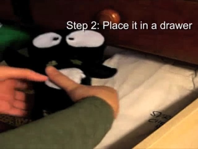
    antisocial cat_prototype 006 code iteration 

    So, yeah, I figured out what the problems were and finally made the servo work as the way I want! Hooray!
    When the toy detects me (using sensor), it would turn its head and stay at that position until it detects me again and turns its head.

    http://vimeo.com/moogaloop.swf?clip_id=2414067&server=vimeo.com&show_title=1&show_byline=1&show_portrait=0&color=&fullscreen=1
    prototype 006 code iteration from maze on Vimeo.

    And here is the code:

    ———————————————————–

    #include <Servo.h>

    Servo myservo; //create servo object to control a servo
    int sensor = 0;  // analog pin used to connect the sensor
    int motorPin=11;
    int val;    // variable to read the value from the analog pin
    boolean status=0; //status of detecting
    int counter=0;

    void setup()
    {
      myservo.attach(11);
      myservo.setMaximumPulse(2200);
     
      Serial.begin(9600);           // set up Serial library at 9600 bps
      pinMode(sensor, INPUT);
      //pinMode(relay, OUTPUT);
      pinMode(motorPin, OUTPUT);
      myservo.setMaximumPulse(2000);
      myservo.setMinimumPulse(700);

      Serial.print("Ready\n");
    }//end of setup

    int getSensor() {
      val = analogRead(sensor);            // reads the value of the potentiometer (value between 0 and 1023)
      val = map(val, 0, 1023, 0, 179);     // scale it to use it with the servo (value between 0 and 180)

      val=max(val,5);
      val=min(val,180);

      return val;
    } //end of getSensor

    void myRefresh(int delayTime){
      for(int i=0; i < delayTime/20; i++){ //delay is the total ms delay we want, 20 is the delay per iteration of the loop 
          Servo::refresh(); 
          delay(20);
      }
    }

    int move0(){
      Serial.print("servo position 0\n");
      myservo.write(0);
      //Servo::refresh();
      myRefresh(100);
    }//end of move0

    int move90(){
      Serial.print("servo position 90\n");
      myservo.write(90);
      //Servo::refresh();
      myRefresh(100);
    }//end of move90

    int move180(){
      Serial.print("servo position 180\n");
      myservo.write(180);
      //Servo::refresh();
      myRefresh(100);
    }//end of move180

    void loop()
    {
        val=getSensor();
        Serial.println(val);
       
       
        if (val>20){
          if(status==0){
             move180();
             myRefresh(1000);                           // waits for the servo to get there
             counter++;
          }

          else if(status==1){
            move0();
            myRefresh(1000);
            counter++;
          }//end of else

        }//end of if
       
        if(counter%2!=0){
          status=1;
        }else{
        status=0;
        }

        //myservo.write(getSensor());
        //Serial.println(getSensor());
        //delay(15);

      Servo::refresh();
    }

    —————————————————————————–

    I defined a function myRefresh() to make sure the servo would be refreshed every 20ms.
    Then I added 3 moving functions with different angles.
    The tricky part was that how to make servo stop and turn to reverse direction when the sensor detects someone again. By using 2 variables counter and status, I made servo turn to position 180 when the counter is even and turn to position 0 when it is odd.

    In this week, I’ll try to put the prototype that I have so far into the body of my plush prototype.
    The focus of the testing this week will be:
    – redesign the character for prototyping (make it big enough to put all my electronics)
    – building/ sewing the plush toy
    – make the toy’s head move! Think about materials, the skeleton, connections… etc.

     
  • Yury Gitman 1:00 am on December 3, 2008 Permalink | Reply  

    12 Quack! 

    After a long fight with win bound chip and arduino and bubbles…, I finally heard it quack!

    http://vimeo.com/moogaloop.swf?clip_id=2413709&server=vimeo.com&show_title=1&show_byline=1&show_portrait=0&color=&fullscreen=1
    Quack! from Hsiang Ju Hung on Vimeo.

    Here’s the code:
    // Input settings
    int analogPin = 3;   // ir sensor connected to analog pin 3
    int val = 0;         // variable to store the read value

    // Digital pin settings
    int aOut = 9;   // Play pin connected to digital pin 9

    // Variables
    int aVal = 0;   // Variables to store the input from the ir sensor

    int DEBUG = 1; // Set to 1 to turn on debugging output

    int average[100]; // Averaging Code setting
    byte counter = 0;

    void setup()
    {
      pinMode(aOut, OUTPUT);   // sets the pin as output

      if (DEBUG) {

        Serial.begin(9600);     // Open serial communication for reporting
      }
    }

    //Main program
    void loop(){
      val = analogRead(analogPin);

      //Averaging Code start
      average[counter] =  val;
      byte c;
      int total = 0;
      for(c = 0;c<100;c++){
        total += average[c];
      }
      int averaged = total / 100;
      Serial.println(averaged);
      counter = (counter + 1) % 100; //Averaging Code. modified from Dave Millis example

      if(val < 300){       
        analogWrite(aOut, 0);
        delay(1500);
        analogWrite(aOut, 255);
        delay(100);
      }
      else{                  
        analogWrite(aOut, 255);
      }
        if (DEBUG) {      // if we want to read the output
        DEBUG+=1;      
        if(DEBUG>100){  //print every hunderd loops
          DEBUG = 1;    // reset the counter
      Serial.print(val);
        }}
    }

    And here is the new win bound recorder which is smaller, more solid, and works as well as the old one. It sounds actually better because  I got a bigger speaker for it.
    Dscn0743

     
  • Yury Gitman 5:24 pm on December 2, 2008 Permalink | Reply  

    Birdie/Qwail work in progress… 

    I’ve scrapped the Winbond, which is both good and bad. The Winbond would have been great for making bird sounds, but the Arduino Mini is so much more compact and easy to work with. It makes sound too, but the computery noises it makes are not very bird-like. In fact, they’re just downright annoying.

    I’m using the Play Melody code from an Arduino tutorial to get started. I had to add a couple of extra octaves (by halving the frequency of each tone for each octave), and now I’m working on getting the melody to play at the appropriate time.

    Right now my code will play a little ditty after 15 seconds if someone is not in front of the IR sensor. I need more parameters, but it’s not bad for a proof of concept. Consider is an implementation prototype.

    My code is after the jump, by the way

    Some photos:

    The Whole Mess

    Img_5597

    Here is my arudino mini, hooked up to the arduino as a usb connector. Also featured within the mess of wires is an IR sensor, a speaker (bigger than the one I’ll end up using, actually), and some fine LEDS to help me figure out what’s going on when). The Red LED comes on when the IR is on and reading something is close, and Yellow LED comes on when the IR is reading that nothing is in front of it anymore.


    A Close Up

    Img_5609

    This is just a close up shot of the Arduino Mini, connected to things. I’ll be taking it off of the bread board as soon as I’m happy with my code. Until then, it stays, which unfortunately is holding me back from making Birdie look and feel prototypes.

    A video is coming soon!!

    (More …)

     
  • Yury Gitman 1:31 pm on December 2, 2008 Permalink | Reply  

    Catertainer Circuit + Code 

    The code finally works!

    The Catertainer has 10 taunts, and every minute, if it isn’t played with, it will say one of the taunts.

    Here is an example of one of the taunts.

    http://vimeo.com/moogaloop.swf?clip_id=2407870&server=vimeo.com&show_title=1&show_byline=1&show_portrait=0&color=&fullscreen=1
    Catertainer Circuit from Mouse & the Billionaire on Vimeo.

    I finally got the Wee from Sparkfun, so I’ll be transferring the whole circuit to the new (much smaller) circuit, soon.

    fun!

    (More …)

     
  • Yury Gitman 9:12 am on December 2, 2008 Permalink | Reply  

    Arduino Trick: Treating Digital like Analog 

    In response to Katrina’s great tip about the multiplexer I thought I would pass this little trick on as well.

    With only a few simple lines of code you too can use your digital inputs to read analog data. Below is the function. Just copy and paste the code before your void loop(), then call it with digiAnalog(pin). It’s pretty easy. Continue reading to see the code:

    (More …)

     
  • Yury Gitman 1:38 am on December 2, 2008 Permalink | Reply  

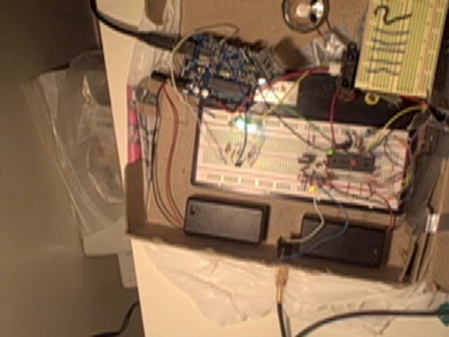
    Making some progress??? 

    So here’s what I’ve got going so far…it doesn’t look like much right now, but it will make a huge difference once I actually have it all set up in the real trash bin I intend to use. Right now I’m just trying to get everything to work.

    I’ve go the IR sensors detecting which bin (recycling or waste) was used, and the Winbond chip changes tracks and plays back the appropriate sound depending which side was just used. I’m having a bit of a problem with the Windbond chip, though. When it needs to change tracks it won’t play back the sound after it has moved forward. It’ll only play the sound the next time that side of the bin is used. I can’t figure out how to fix it in my code, but I don’t think it’s a huge problem…just strange. My code is posted at the end of this blog post.

    I also have the Arduino counting how many times each side has been used. A green or yellow LED will light up when one side is used more than the other (green = you’ve recycled more, yellow = you’ve wasted more).

    Alos, I assembled my XBee transceivers. It took FOREVER to solder everything – I even got injured in the process (one of the pins got shoved under my fingernail…awesome.). I haven’t set them up to work yet…but that’s going to happen in the next day or two. For now, all data from the bin can be seen through the serial reader in Arduino. I’ve posted a screenshot of it below.

    Lastly, I started playing with some big FSR’s to use as a rough scale/weight measurement for now. Next task for me is to figure how I’m going to normalize their numbers in my code…I have no clue how I’m going to do that…

    Here’s some pics:

    Insidebin

    The inside of my ‘bin’…not pretty, but semi-functional at least!

    Xbeeboardtop

    Xbeeboardbottom

    Mountedxbee

    Had to show off my awesome soldering job…male and female header pins all in a row, just so I can mount a silly XBee on it.

    Serialscreenshot

    Screen shot of Arduino serial reader showing my bin data…with some lovely notes included in red.

    http://vimeo.com/moogaloop.swf?clip_id=2403729&server=vimeo.com&show_title=1&show_byline=1&show_portrait=0&color=&fullscreen=1
    PING Documentation from Katrina Bekessy on Vimeo.

    Current problems I’m having:

    -getting my Windbond chip to change tracks and play back the sound right after
    -normalizing my FSR inputs to numbers that actually mean something
    -keeping the stupid IR sensors consistent. Everytime I turn them on they start with different readings than before

    Next things I need to do:

    -include FSR’s and photoresistor (for lid of bin) with rest of my circuit using a multiplexer
    -get XBee’s to send bin data to computer wirelessly
    -build working circuit into actual trashbin
    -refine code to make readings more accurate

    Am in way over my head? Yes, yes I am…

    Here’s my long Arduino code thus far. I’m sure it could be written much more succinctly/efficiently…

    #define NUMREADINGS1 10
    #define NUMREADINGS2 10
    #define NUMREADINGS3 10
    #define NUMREADINGS4 10

    int readings1[NUMREADINGS1];
    int index1 = 0;
    int total1 = 0;
    int average1 = 0;

    int readings2[NUMREADINGS2];
    int index2 = 0;
    int total2 = 0;
    int average2 = 0;

    int readings3[NUMREADINGS3];
    int index3 = 0;
    int total3 = 0;
    int average3 = 0;

    int readings4[NUMREADINGS4];
    int index4 = 0;
    int total4 = 0;
    int average4 = 0;

    int IR1 = 0;
    int valIR1 = 0;

    int IR2 = 1;
    int valIR2 = 0;

    int IR3 = 3;
    int valIR3 = 0;

    int IR4 = 4;
    int valIR4 = 0;

    boolean readBin = true;

    int playPin = 2;
    int fwdPin = 3;
    int trackCount = 1;

    int wasteCount = 0;
    int recCount = 0;
    int greenLED = 4;
    int yellowLED = 5;

    void setup()
    {
      Serial.begin(9600);
     
      pinMode(playPin, OUTPUT);
      pinMode(fwdPin, OUTPUT);
      pinMode(greenLED, OUTPUT);
      pinMode(yellowLED, OUTPUT);
     
      for (int i = 0; i < NUMREADINGS1; i++){
        readings1[i] = 0;
      }
     
      for (int j = 0; j < NUMREADINGS2; j++){
        readings2[j] = 0;
      }
     
      for (int h = 0; h < NUMREADINGS3; h++){
        readings3[h] = 0;
      }
     
      for (int k = 0; k < NUMREADINGS4; k++){
        readings4[k] = 0;
      }
    }

    void loop()
    {
      digitalWrite(fwdPin, HIGH);
      digitalWrite(playPin, HIGH);
     
      if(readBin == true){
        total1 -= readings1[index1];
        readings1[index1] = analogRead(IR1);
        total1 += readings1[index1];
        index1 = (index1 + 1);
     
        if (index1 >= NUMREADINGS1){
          index1 = 0;
        }
     
        average1 = total1 / NUMREADINGS1;
     
        total2 -= readings2[index2];
        readings2[index2] = analogRead(IR2);
        total2 += readings2[index2];
        index2 = (index2 + 1);
     
        if (index2 >= NUMREADINGS2){
          index2 = 0;
        }
     
        average2 = total2 / NUMREADINGS2;
     
        total3 -= readings3[index3];
        readings3[index3] = analogRead(IR3);
        total3 += readings3[index3];
        index3 = (index3 + 1);
     
        if (index3 >= NUMREADINGS3){
          index3 = 0;
        }
     
        average3 = total3 / NUMREADINGS3;
     
        total4 -= readings4[index4];
        readings4[index4] = analogRead(IR4);
        total4 += readings4[index4];
        index4 = (index4 + 1);
     
        if (index4 >= NUMREADINGS4){
          index4 = 0;
        }
     
        average4 = total4 / NUMREADINGS4;
     
        if(average1 > 365 || average2 > 365){
          readBin = false;
          recCount ++;
          
          Serial.print("waste");
          Serial.println();
          Serial.print(average1);
          Serial.println();
          Serial.print(average2);
          Serial.println();
          Serial.print(recCount);
          Serial.println();
          
          if(trackCount == 1){
            playBack();
          } else {
            digitalWrite(fwdPin, LOW);
            delay(300);
            digitalWrite(fwdPin, HIGH);
            trackCount = 1;
            playBack();
          }
        }
     
        if(average3 > 365 || average4 > 365){
          readBin = false;
          wasteCount ++;
                
          Serial.print("recycle");
          Serial.println();
          Serial.print(average3);
          Serial.println();
          Serial.print(average4);
          Serial.println();
          Serial.print(wasteCount);
          Serial.println();
          
          if(trackCount == 2){
            playBack();
          } else {
            digitalWrite(fwdPin, LOW);
            delay(300);
            digitalWrite(fwdPin, HIGH);
            trackCount = 2;
            playBack();
          }
        }
      }
      if(recCount > wasteCount){
        digitalWrite(greenLED, HIGH);
        digitalWrite(yellowLED, LOW);
      }
      else if(wasteCount > recCount){
        digitalWrite(yellowLED, HIGH);
        digitalWrite(greenLED, LOW);
      }
      else {
        digitalWrite(yellowLED, LOW);
        digitalWrite(greenLED, HIGH);
      }
    }

    void playBack(){
      digitalWrite(playPin, LOW);
      delay(300);
      digitalWrite(playPin, HIGH);
      delay(3000);
      readBin = true;
    }

     
  • Yury Gitman 11:54 pm on November 30, 2008 Permalink | Reply  

    antisocial cat_ servo prototype 

    Prototype 005
    Materials: PIC16F88, breadboard, servo, pot
    Notes:
    – The servo could keep turning left and right, but I couldn’t control its speed and directions.
    – I found that Arduino has a servo library that is easy to use for controlling servos. So I decided to switch to Arduino board.

    http://vimeo.com/moogaloop.swf?clip_id=2297781&server=vimeo.com&show_title=1&show_byline=1&show_portrait=0&color=&fullscreen=1
    servo test from maze on Vimeo.

    Prototype 006
    Materials: Arduino, servo, breadboard, IR sensor
    Notes:
    – In the very beginning, the range of IR sensor was too small. Thus the servo only moved when I almost touched the sensor. Here I scaled the value of IR sensor from 0-1023 to 0-179.
    Img_1905_2

    – The servo had a problem of drawing too much current.

    Picture_1_3

    – So I did iteration by separating power supply for the servo, but joined the grounds of the two power supplies. I also added decoupling capacitors to stabilize my voltage regulator.

    Img_1911

    Img_1912

    Img_1916

    Img_1917

    http://vimeo.com/moogaloop.swf?clip_id=2391917&server=vimeo.com&show_title=1&show_byline=1&show_portrait=0&color=&fullscreen=1
    prototype_arduino+servo+ir sensor from maze on Vimeo.

    – Here is the code:
    ——————————————————————————————————–
    #include <Servo.h>

    Servo myservo; //create servo object to control a servo
    int sensor = 0;  // analog pin used to connect the sensor
    int motorPin=11;
    int val;    // variable to read the value from the analog pin

    void setup()
    {
      myservo.attach(11);
      myservo.setMaximumPulse(2200);
     
      Serial.begin(9600);           // set up Serial library at 9600 bps
      pinMode(sensor, INPUT);
      //pinMode(relay, OUTPUT);
      pinMode(motorPin, OUTPUT);
      myservo.setMaximumPulse(2000);
      myservo.setMinimumPulse(700);

      Serial.print("Ready\n");
    }

    int getSensor() {
      val = analogRead(sensor);            // reads the value of the potentiometer (value between 0 and 1023)
      val = map(val, 0, 1023, 0, 179);     // scale it to use it with the servo (value between 0 and 180)

      val=max(val,5);
      val=min(val,180);

      return val;
    } //end of getSensor

    /*
    int moveFoward() {
      analogWrite(motorPin, getSensor());
      delay(1000);
      digitalWrite(motorPin, LOW);
      delay(1000);
      //digitalWrite(relay, HIGH);
      //Serial.println(getIR());
      delay(1000);
    }

    int moveBackward() {
      analogWrite(motorPin, getSensor());
      delay(1000);
      digitalWrite(motorPin, LOW);
      delay(1000);
      //digitalWrite(relay, LOW);
      //Serial.println(getIR());
      delay(1000);
    }
    */

    void loop()
    {
    /*
        val=getSensor();
        if (val<140){
            val=180;
            myservo.write(val);                  // sets the servo position according to the scaled value
            delay(15);                           // waits for the servo to get there
        }//end of if

      while(getSensor()>30){
        myservo.write(getSensor());
        Serial.println(getSensor());
        delay(15);
      }//end of while
    */
        myservo.write(getSensor());
        Serial.println(getSensor());
        delay(15);

      //moveFoward();
      //moveBackward();
      Servo::refresh();
    }
    ————————————————————————————————-
    – I tried to pause the servo after every time it turns by expanding the delay time of myservo.write(). However, its movement became unpredictable. Then I tried moveFoward() and moveBackward() above, but they didn’t work well either.
    – Another problem I have is the click sound of servo. I was wondering if extreme turning angles like 179 or 180 caused those noise.

     
    • M Bethancourt 8:51 am on December 2, 2008 Permalink | Reply

      Your Servo is probably fine. The USB Over Current notice means that there is a short somewhere in your circuit.

    • M Bethancourt 8:53 am on December 2, 2008 Permalink | Reply

      ps
      That’s a damn cute anti-social cat you’ve got up there.

  • Yury Gitman 8:03 pm on November 30, 2008 Permalink | Reply  

    How May I Help You?: Code 

    The code is very simple.  Take a look by clicking the following link.

    (More …)

     
  • Yury Gitman 8:58 pm on November 9, 2008 Permalink | Reply  

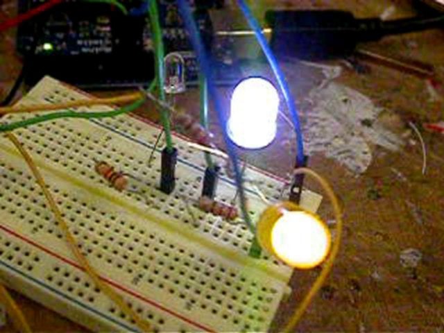
    07 IR sensor + Recorder 

    Dscn0408

    I set three functions for different range of distance as fallowing:
    1.about 50-80cm: Play
    2.about 15-50cm: Play and fwd
    3.about under 15cm: Play and change volume

    Here’s the video where I use three leds to test if the code works first.

    http://vimeo.com/moogaloop.swf?clip_id=2156376&server=vimeo.com&show_title=1&show_byline=1&show_portrait=0&color=&fullscreen=1
    LED + IR from Hsiang Ju Hung on Vimeo.

    The left led is Play, the middle one is Fwd, and the right one is Vol.
    So, it works fine with pin high and low/led on and off.
    And here is the code.Download ir_recorder.rtf

    Then I put the connectors  to the recorder.
    Here is what happen on level 1 and 2.

    http://vimeo.com/moogaloop.swf?clip_id=2156723&server=vimeo.com&show_title=1&show_byline=1&show_portrait=0&color=&fullscreen=1
    Level First to Second from Hsiang Ju Hung on Vimeo.

    Level 3, which will keep changing volume on the same sound file if you stay longer.

    http://vimeo.com/moogaloop.swf?clip_id=2156675&server=vimeo.com&show_title=1&show_byline=1&show_portrait=0&color=&fullscreen=1
    Level Third: keeps changing volume from Hsiang Ju Hung on Vimeo.

     
  • Yury Gitman 5:49 pm on November 4, 2008 Permalink | Reply  

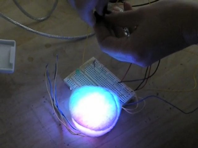
    Making The Windbond Sing! 

    Just wave you hand in the air!

    Continue reading to see the code.

    (More …)

     
  • Yury Gitman 5:07 pm on November 4, 2008 Permalink | Reply  

    IRSensor + Winbond Chip 

    Okay.. it was kinda working… 

    The code that I modified is below:

    (More …)

     
  • Yury Gitman 1:12 am on November 4, 2008 Permalink | Reply  

    Winbond + Arduino V1 

    http://vimeo.com/moogaloop.swf?clip_id=2137610&server=vimeo.com&show_title=1&show_byline=1&show_portrait=0&color=&fullscreen=1
    Winbond + Arduino from Jennifer Dopazo on Vimeo.

    The first attempt…

    (More …)

     
c
Compose new post
j
Next post/Next comment
k
Previous post/Previous comment
r
Reply
e
Edit
o
Show/Hide comments
t
Go to top
l
Go to login
h
Show/Hide help
shift + esc
Cancel