Hardware Photos
-
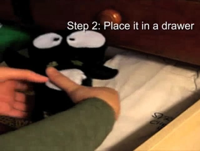
Antisocial toy
After solving the movement issue of servo, I started thinking about how to put all these…
-
Hello, How May I Help You?
Do you often have guests over and wonder what they’re doing when you’re not looking? Perhaps,…
-
Compy: A peek inside
Finally, Compy is up and working! Here are some photos of his guts, and his code…
-

PING. What will it say about you?
PING is a smart trash/recycling bin that tracks your trash activity and reports it online. His…
-
Lets get it on Lamp. (bringin the heat…all night long!)
So I got the code and circuitry to all work correctly for my "Let’s Get It…
-

12 Quack!
After a long fight with win bound chip and arduino and bubbles…, I finally heard it…
-
Birdie/Qwail work in progress…
I’ve scrapped the Winbond, which is both good and bad. The Winbond would have been great…
-

Catertainer Circuit + Code
The code finally works! The Catertainer has 10 taunts, and every minute, if it isn’t played…
-
Wee!
The Wee I ordered from Sparkfun just came in, and it is ridiculously small. I just…
-
Making some progress???
So here’s what I’ve got going so far…it doesn’t look like much right now, but it…
-
antisocial cat_ servo prototype
Prototype 005Materials: PIC16F88, breadboard, servo, pot Notes:– The servo could keep turning left and right, but…
-

zipper test
Here’s my first zipper test on a breadboard before its sewn into the pants. http://vimeo.com/moogaloop.swf?clip_id=2279427&server=vimeo.com&show_title=1&show_byline=1&show_portrait=0&color=&fullscreen=1zipper test…
-
07 IR sensor + Recorder
I set three functions for different range of distance as fallowing:1.about 50-80cm: Play2.about 15-50cm: Play and…
-

Winbond + Arduino V1
http://vimeo.com/moogaloop.swf?clip_id=2137610&server=vimeo.com&show_title=1&show_byline=1&show_portrait=0&color=&fullscreen=1Winbond + Arduino from Jennifer Dopazo on Vimeo. The first attempt…
-
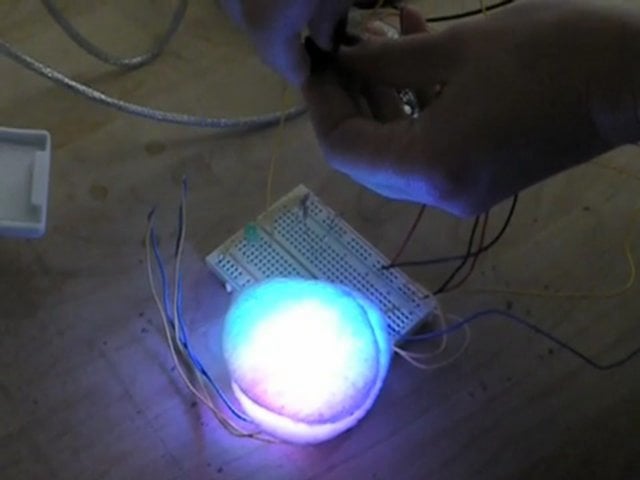
IR sensor + 3 LEDS
Here’s the fine video of my IR sensor actually working!! http://vimeo.com/moogaloop.swf?clip_id=2093728&server=vimeo.com&show_title=1&show_byline=0&show_portrait=0&color=00ADEF&fullscreen=1Another IR sensor + 3 LEDS…
-

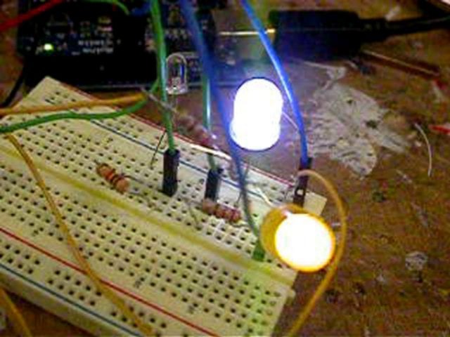
IR sensor with three LEDs
http://vimeo.com/moogaloop.swf?clip_id=2074883&server=vimeo.com&show_title=1&show_byline=1&show_portrait=0&color=&fullscreen=1IR sensor with three LEDs from Jennifer Dopazo on Vimeo.
-
Audio Recorder
Here is the push buttons and LED lights: Here is the speaker cover/with plastic tube beneath…
You must be logged in to post a comment.