February 2009
-

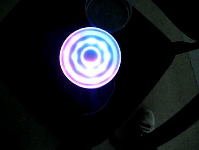
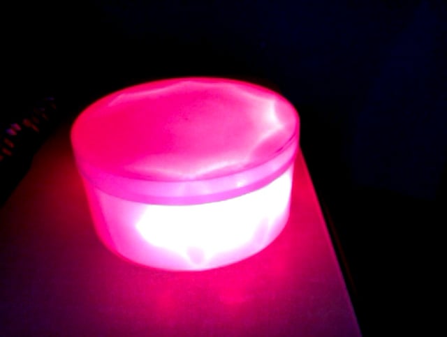
LED time piece • v03 • PWM
Went minimalist for this iteration of my timepiece. My new role for this prototype is a…
-
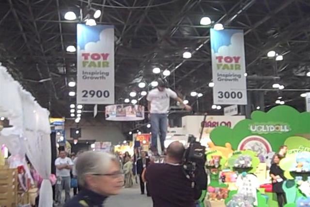
Toy fair video!
http://vimeo.com/moogaloop.swf?clip_id=3376456&server=vimeo.com&show_title=1&show_byline=1&show_portrait=0&color=&fullscreen=1int’l toy fair 2009 from j saavedra on Vimeo.
-
broken – can we talk about this?
int ledPins[] = { 3, 5, 6, 9, 10, 11 }; // an array of pin…
-
Ira / Still counting sheep2…
I find the way to make my counting sheep prototype as a more compact book. I…
-
Passage of time v2.5 with Switches
I added switches to the fourth iteration of the passage of time. 1 rocker switch for…
-
Ira / Still counting sheep…
Still counting sheep as a time passage project, but I decided try a totally different iteration.I've…
-
:::Switches:::
There are a few aspects of having fun with switches that we did not cover during…
-
time gesture iteration – new prototype
I've shelved the cocoon prototype for the time being, in favor of a model which better…
-
:::Reading from Code:::
:::Reading from CODE::: What were the specific technical issues (referring to wire and resistance) that prevented…
-

Student Lecture 3
Steve, Thai, Bruce – AnalogWrite, PWM, Fading LED’s, Multiple LED’s via PWM, Tri-Color LEDs, Cases, Switch…
-
Student Lecture Sections
_1_____Yury___________________________2/13/09_Structure: Void Setup, Void Loop, Functions: pinMode, digitalWrite, digitalRead, analogRead, analogWrite, Syntax: (semicolon),{} (curly braces),//…
-
Prototype 3
New iteration of the the time passing LED prototypes. Definitely getting very close to a finished…
-
LED Passage of Time – Prototype 3
On this prototype a majority of my time was assembling the little structure that supports all…
-
:::Fun with switches:::
Fun with switches link Where to buy your witches: Sparkfun is great for mini switches For…
-
Library Research
My library research yielded several results of time based media. The first example I found was…
-
Passage of Time / Ira Goldberg
After a very long night of work and burned fingers I finally finished this new iteration.I've…
-
Telegraph – 2/13/09 class paper
What were the specific technical issues referring to wire and resistance, that presented the early telegraph…
-
Code class paper
What were the specific technical issues (refering to wire + resistance) that prevented the early telegraph…
You must be logged in to post a comment.