Updates from November, 2011 Toggle Comment Threads | Keyboard Shortcuts

  • Unknown's avatar

    Jun Sik (Jason) Kim 6:38 am on November 9, 2011 Permalink | Reply  

    Jason Kim Midterm: Stupid Pumpkin 

    1) Project Name: Stupid Pumpkin

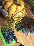
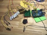
    The concept of the Stupid Pumpkin is relatively straightforward. It’s a pumpkin that looks stupid and a pumpkin that people would want to hit. Using two tilt sensors, I could detect if the pumpkin was hit from the left or from the right. If hit from the right side, the servo motor turns in a clockwise direction (counter clockwise if hit from left) and the Stupid Pumpkin makes a sad face and starts to cry. The LEDs representing the mouth of the pumpkin are controlled by a shift register. The eyes of the pumpkin are RGB LEDs that change color every time the pumpkin is hit. Near the nose (fading superbright blue LED) of the pumpkin is also a photocell that detects if the pumpkin’s nose is covered or if the lights are turned off. If the nose is covered or lights are turned off, the Stupid Pumpkin starts to cry as it is lonely and frightened. The inside of the pumpkin are all wires and circuit boards and uses no bread boards. Circuit boards are screwed on the inside wall of the pumpkin. The Arduino is powered by a 9V battery pack.

    2) A photo of the electronics and final project

    3) A short video demonstrating it

    4) The Arduino code

    <pre>//Midterm Pumpkin Jason Kim
    
    //Photocell
    int photocellPin = A3;
    int photocellReading;
    
    //Servo Motor
    #include <Servo.h>
    Servo myServo;
    int noTurn = 90;
    
    //Shift Register 75HC595
    int SER_Pin = 11;   //pin 14 on the 75HC595 bluewire
    int RCLK_Pin = 8;  //pin 12 on the 75HC595 greenwire
    int SRCLK_Pin = 12; //pin 11 on the 75HC595 yellowwire
    #define number_of_74hc595s 1
    #define numOfRegisterPins number_of_74hc595s * 8
    
    //Pumpkin eyes
    const int redPin = A0;
    const int greenPin = A1;
    const int bluePin = A2;
    const boolean invert = true;
    
    int color = 0;
    int R, G ,B;
    
    //Pumpkin tear eyes
    int eyePin[] = {
      6,3};
    
    int eyePin2[] = {
      9,10};
    
    int brightness2 = 0;
    int brightness3 = 0;
    
    //Pumpkin nose
    int brightness = 0;
    int fadeAmount = 5;
    int nosePin = 5;
    
    //Pumpkin hit (tilt sensor)
    int tiltPin[] = {
      7,4};
    int tiltState = 0;
    int tiltState2 = 0;
    
    //test led
    int testPin = 13;
    
    boolean registers[numOfRegisterPins];
    
    void setup(){
      Serial.begin(9600);
      myServo.attach(2);
      myServo.write(noTurn);
      pinMode(SER_Pin, OUTPUT);
      pinMode(RCLK_Pin, OUTPUT);
      pinMode(SRCLK_Pin, OUTPUT);
      pinMode(nosePin, OUTPUT);
      for(int i = 0; i<2; i++){
        pinMode(tiltPin[i], INPUT);
      }
      for(int j = 0; j<2; j++){
        pinMode(eyePin[j],OUTPUT);
      }
      for(int k = 0; k<2; k++){
        pinMode(eyePin2[k],OUTPUT);
      }
      clearRegisters();
      writeRegisters();
    }       
    
    //set all register pins to LOW
    void clearRegisters(){
      for(int i = numOfRegisterPins - 1; i >=  0; i--){
        registers[i] = LOW;
      }
    }
    void writeRegisters(){
      digitalWrite(RCLK_Pin, LOW);
      for(int i = numOfRegisterPins - 1; i >=  0; i--){
        digitalWrite(SRCLK_Pin, LOW);
        int val = registers[i];
        digitalWrite(SER_Pin, val);
        digitalWrite(SRCLK_Pin, HIGH);
      }
      digitalWrite(RCLK_Pin, HIGH);
    }
    
    void setRegisterPin(int index, int value){
      registers[index] = value;
    }
    
    void loop(){
      tiltState = digitalRead(tiltPin[0]);
      tiltState2 = digitalRead(tiltPin[1]);
      photocellReading = analogRead(photocellPin);
      photocellReading = 1023 - photocellReading;
      if (photocellReading > 500 && photocellReading < 600){
        myTear();
      }
      Serial.print("Photocell reading = ");
      Serial.println(photocellReading);
      //Pumpkin Eyes
      myEye();
      //Pumpkin Nose
      myNose();
      //Pumpkin Hit
      myHit();
      //Pumpkin Mouth
      myHappy();
      writeRegisters();
      if(tiltState == HIGH){
        myServo.write(111);
        mySad();
        myEyeHit();
        writeRegisters();
        myTear();
        delay(500);
        myServo.write(noTurn);
      }
      if(tiltState2 == HIGH){
        myServo.write(71);
        mySad();
        myEyeHit();
        writeRegisters();
        myTear();
        delay(500);
        myServo.write(noTurn);
      }
    }
    void myHappy(){
      setRegisterPin(0, HIGH);
      setRegisterPin(3, HIGH);
      setRegisterPin(5, HIGH);
      setRegisterPin(6, HIGH);
      setRegisterPin(1, LOW);
      setRegisterPin(2, LOW);
      setRegisterPin(4, LOW);
      setRegisterPin(7, LOW);
    }
    void mySad(){
      setRegisterPin(1, HIGH);
      setRegisterPin(2, HIGH);
      setRegisterPin(4, HIGH);
      setRegisterPin(7, HIGH);
      setRegisterPin(0, LOW);
      setRegisterPin(3, LOW);
      setRegisterPin(5, LOW);
      setRegisterPin(6, LOW);
    }
    void myNose(){
      analogWrite(nosePin, brightness);
      brightness = brightness + fadeAmount;
      if (brightness == 0 || brightness == 255){
        fadeAmount = -fadeAmount;
      }
      delay(30);
    }
    void myHit(){
      if(tiltState == HIGH){
        digitalWrite(testPin, HIGH);
      }
      else if(tiltState2 == HIGH){
        digitalWrite(testPin, HIGH);
      }
      else{
        digitalWrite(testPin, LOW);
      }
    }
    void myTear(){
      for(int i =0; i < 2; i++){
        //one LED fade
        for(int brightness2 = 0; brightness2 <= 255; brightness2 +=5){
          analogWrite(eyePin[i], brightness2);
          //      analogWrite(eyePin2[i],brightness2);
          delay(10);
        }
        for(int brightness2 = 255; brightness2 >= 0; brightness2 -=5){
          analogWrite(eyePin[i],brightness2);
          //      analogWrite(eyePin2[i],brightness2);
          delay(10);
        }
      }
    }
    void myLeftTear(){
      for(int i = 0; i < 2; i++){
        //one LED fade
        for(int brightness3 = 0; brightness3 <= 255; brightness3 +=5){
          //      analogWrite(eyePin[i],brightness2);
          analogWrite(eyePin2[i],brightness3);
          delay(10);
        }
        for(int brightness3 = 255; brightness3 >= 0; brightness3 -=5){
          //      analogWrite(eyePin[i],brightness2);
          analogWrite(eyePin2[i],brightness3);
          delay(10);
        }
      }
    }
    void myEye(){
      int brightnessEye = 255;
      hueToRGB(color, brightnessEye);
      analogWrite(redPin, R);
      analogWrite(greenPin, G);
      analogWrite(bluePin, B);
      if(color > 255){
        color = 0;
      }
      delay(10);
    }
    void myEyeHit(){
      int brightness = 100;
      hueToRGB(color, brightness);
      analogWrite(redPin, R);
      analogWrite(greenPin, G);
      analogWrite(bluePin, B);
      color+=60;
      if(color > 255){
        color = 0;
      }
      delay(10);
    }
    void hueToRGB( int hue, int brightness){
      unsigned int scaledHue = (hue * 6);
      unsigned int segment = scaledHue / 256; //segment 0 to 5 round the color wheel
      unsigned int segmentOffset = scaledHue - (segment * 256); //position within segment
      unsigned int complement = 0;
      unsigned int prev = (brightness * ( 255 - segmentOffset)) / 256;
      unsigned int next = (brightness * segmentOffset) / 256;
      if(invert){
        brightness = 255-brightness;
        complement = 255;
        prev = 255-prev;
        next = 255-next;
      }
      switch(segment ){
      case 0: //red
        R = brightness;
        G = next;
        B = complement;
        break;
      case 1: //yellow
        R = prev;
        G = brightness;
        B = complement;
        break;
      case 2: //green
        R = complement;
        G = brightness;
        B = next;
        break;
      case 3: //cyan
        R = complement;
        G = prev;
        B = brightness;
        break;
      case 4: //blue
        R = next;
        G = complement;
        B = brightness;
        break;
      case 5: //magenta
      default:
        R = brightness;
        G = complement;
        B = prev;
        break;
      }
    }
    
     
  • Unknown's avatar

    aisencc 4:03 am on November 9, 2011 Permalink | Reply  

    Toccata CalaBach 


    The concept behind this pumpkin was inspired by the Toccata in Fugue D Minor by Bach. The teeth of the pumpkin are white keys/ switches, that when pressed to the bottom surface close the circuit and play a note through a piezo buzzer. If the first and the last key are both pressed at the same time, a short introduction of the Toccata in Fugue plays. The light of the pumpkin turns on at night, once a photoresistor reads values that are low enough to mean darkness. A little stuffed dead guy accompanies Toccata CalaBach, representing Johann Sebastian.


    // CODE:

    int photo= 0;
    int led = 2;
    int key1 = 3;
    int key2 = 4;
    int key3 = 5;
    int key4 = 6;
    int key5 = 7;
    int key6 = 8;
    int speakerOut = 9;

    int debounce = 10;

    int state= LOW;
    int lastkeyvalue = LOW; // we start, assuming no motion detected
    int val= 0;
    int val1 = 0;
    int val2 = 0;
    int val3 = 0;
    int val4 = 0;
    int val5 = 0;
    int val6 = 0;
    // variable for reading the key status
    //******************************************************************************
    // TONES ==========================================
    // Start by defining the relationship between
    // note, period, & frequency.
    int c= 3830; // 261 Hz
    int d= 3400; // 294 Hz
    int e= 3038; // 329 Hz
    int f= 2864; // 349 Hz
    int g= 2550; // 392 Hz
    int a= 2272; // 440 Hz
    int b= 2028; // 493 Hz
    int C= 1912; // 523 Hz
    // Define a special note, ‘R’, to represent a rest
    int O= 0;

    // MELODY and TIMING =======================================
    // melody[] is an array of notes, accompanied by beats[],
    // which sets each note’s relative length (higher #, longer note)
    int melody[] = {
    a, g, a, O, g, f, e, d, 3615, d };
    int beats[] = {
    8, 8, 64, 64, 16, 16, 16, 16, 64, 64 };
    int MAX_COUNT = sizeof(melody) / 2; // Melody length, for looping.

    // Set overall tempo
    long tempo = 10000;
    // Set length of pause between notes
    int pause = 1000;
    // Loop variable to increase Rest length
    int rest_count = 100; //<-BLETCHEROUS HACK; See NOTES

    // Initialize core variables
    int tone_ = 0;
    int beat = 0;
    long duration = 0;
    //******************************************************************************

    void setup() {
    pinMode(speakerOut, OUTPUT);
    pinMode(photo, INPUT); //photoresistor Analog
    pinMode(key1, INPUT);
    pinMode(key2, INPUT);
    pinMode(key3, INPUT);
    pinMode(key4, INPUT);
    pinMode(key5, INPUT);
    pinMode(key6, INPUT);
    pinMode(led, OUTPUT);

    Serial.begin(9600);
    }

    void loop(){
    val1 = digitalRead(key1);
    val2 = digitalRead(key2);
    val3 = digitalRead(key3);
    val4 = digitalRead(key4);
    val5 = digitalRead(key5);
    val6 = digitalRead(key6);
    if (val1 == HIGH && val6 == HIGH){
    playSong();
    }else{
    keyTones();
    }
    nightLight();

    }

    void keyTones(){
    Serial.println(“val1”);
    if (val1 == HIGH){
    tone_=c;
    duration= 640000;
    playTone();
    Serial.println(“YES = 1”);
    }
    if (val2 == HIGH){
    tone_=d;
    duration= 640000;
    playTone();
    Serial.println(“YES = 2”);
    }
    if (val3 == HIGH){
    tone_=e;
    duration= 640000;
    playTone();
    Serial.println(“YES = 3”);
    }

    if (val4 == HIGH){
    tone_=f;
    duration= 640000;
    playTone();
    Serial.println(“YES = 4”);
    }
    if (val5 == HIGH){
    tone_=g;
    duration= 640000;
    playTone();
    Serial.println(“YES = 5”);
    }
    if (val6 == HIGH){
    tone_=a;
    duration= 640000;
    playTone();
    Serial.println(“YES = 6”);
    }
    else {
    digitalWrite(speakerOut, LOW);
    }
    if (val1 != lastkeyvalue ){
    delay(debounce);
    val1 = key1;
    }
    lastkeyvalue= val1, val2, val3, val4, val5, val6;

    }

    void nightLight(){
    val= analogRead(photo);
    // Serial.print(val);
    Serial.print(10, BYTE);
    delay(10);

    if (val<400){
    digitalWrite(led, HIGH);
    }else{
    digitalWrite(led, LOW);
    }

    }

    void playSong() {
    // Set up a counter to pull from melody[] and beats[]
    for (int i=0; i 0) { // if this isn’t a Rest beat, while the tone has
    // played less long than ‘duration’, pulse speaker HIGH and LOW
    while (elapsed_time < duration) {

    digitalWrite(speakerOut,HIGH);
    delayMicroseconds(tone_ / 2);

    // DOWN
    digitalWrite(speakerOut, LOW);
    delayMicroseconds(tone_ / 2);

    // Keep track of how long we pulsed
    elapsed_time += (tone_);
    }
    }
    else { // Rest beat; loop times delay
    for (int j = 0; j < rest_count; j++) { // See NOTE on rest_count
    delayMicroseconds(duration);
    }
    }
    }

     
  • Unknown's avatar

    Aneta Genova 6:27 pm on November 7, 2011 Permalink | Reply  

    Midterm Pumpkin by Aneta Genova 

    Castle of the Black Crow

    The pumpkin castle exudes a soft fading light when it is at peace. As soon as somebody approaches the light starts blinking faster. I am using a PIR motion sensor to detect motion for this action. The black crow sits next to its castle and guards its against predators. If you come closer it attacks (using my own hands and imagination here) and the crow’s eyes start blinking, triggered by a tilt switch.


    Code
    // Midterm project Aneta Genova
    // fading LED and motion sensor

    int timer = 500;
    int sensorPin = A0;
    int sensorValue = 0;
    int ledPin = 11;

    void setup()

    {
    pinMode(11, OUTPUT);
    Serial.begin (9600);
    pinMode(ledPin, OUTPUT);
    pinMode(sensorPin, INPUT);
    delay (2000); // it takes the sensor 2 seconds to scan the area around it before it can detect presence.
    }

    void fade(int pin, int start, int finish, int milliseconds)   // fading set up
    {
    uint32_t startMillis = millis();  // remember when we started
    while (true)  // we will ‘break’ when we are done
    {
    uint32_t elapsedTime = millis() – startMillis;  // track the time

    // convert the elapsed time into a brightness range
    int brightness = map(elapsedTime, 0, milliseconds, start, finish);
    analogWrite(pin, brightness);

    // exit when milliseconds have elapsed
    if (elapsedTime >= milliseconds)
    {
    break;
    }
    delay(1);
    }
    }

    void loop()
    {

    //PIR motion sensor is introduced
    sensorValue = analogRead(sensorPin);
    if (sensorValue < 100)
    while(analogRead(sensorPin) < 100)  //execute the command while statement is true
    {
    digitalWrite(11,HIGH);
    delay(200);
    digitalWrite(11,LOW);
    delay(200); // blinks when the motion has been detected
    }
    else
    {

    fade(11, 0, 255, 2000);  // fade led on pin 11 from min to max over three second
    delay(2000);  // hold for 2 seconds
    fade(11, 255, 0, 2000);  // fade pin 11 from max to min over 2 seconds
    delay(1000);  // hold for 1 second

    }
    }

     
  • Unknown's avatar

    Yury Gitman 8:57 pm on November 6, 2011 Permalink | Reply  

    LoL Shield, Soldering and Testing 

    Hi Everyone,
    1)
    If you still need some visual help putting your LOL together see this:
    1.2) 
    Once you get it all soldered up, run this test code linked below before we start the next class.  It will light up all your LED’s:
    2)
    The required reading for next class is:
    3)
    If you want to get more advanced (next weeks homework), the official library for the shield is hosted here:
    The file you want to use is LoLShield V0.2.beta.zip
    a)
    To install this library create a folder in your Arduino folder called “libraries”, if it is not there already.
    b)
    Bring the LoL_Shield V0.2.beta.zip file into this new libraries folder, and unzip it there.
    c)
    restart Arduino and you should be able to see new examples in: File>Examples>LoLShield>
    d)
    Run the Basic_Test and fonttest sketches.
    4)
    There is another great sketch and accompanying libraries called LoL-shield-dynamic-banner, that displays text you type into the serial window.
     
    • josefayala's avatar

      josefayala 6:31 pm on November 7, 2011 Permalink | Reply

      I believe there might be a problem with that sketch- just because of the name…I tried correcting it but it would not let me.
      What do you suggest?

  • Unknown's avatar

    yongjaelee2011 9:19 pm on November 5, 2011 Permalink | Reply  

    Meet the Hallowbot 

    1) Hallowbot

    2) The basic idea of my Hallowbot is that communicates with a user. I put a PIR Motion Sensor that detects a user in the room or the area, and greets with waking up with blue leds on the eyes. Then, if a user gets close enough to the Hallowbot, there will be an animation with yellow leds that triggered by a PhotoCell. The yellow animation is similar that talks to a user. Also, I put a Tilt Sensor that triggered by a user touching Hallowbot’s Antena on the top of the head and change the color of a led light to red.

    3)

    3) A photo of the final project


    4) A short video demonstrating it.


    5) The code you used.

    int inputPin = 2;
    int ledPin = 6; // blue led 1
    int ledPin4 = 7;  // green led 1  
    
    // button 2 animation
    int inputPin2 = 3;
    int ledPin2 = 8;  // yellow led 1
    int ledPin5 = 9;  // yeallow led 2
    int ledPin6 = 10; // yellow led 3
    int ledPin7 = 11;  // yellow led 4
    
    int inputPin3 = 4;
    int ledPin3 = 12;  // red led
    
    /**** motion sensor *****/
    int timer = 500;
    int sensorPin = A0;
    int sensorValue = 0;
    
    /*    photocells */
    int photocellPin = A1;     // the cell and 10K pulldown are connected to a0
    int photocellReading;     // the analog reading from the sensor divider
    int LEDbrightness;        // 
    
    void setup(){
      Serial.begin(9600);
      pinMode(ledPin,OUTPUT);
      pinMode(inputPin,INPUT);
    
      pinMode(ledPin2,OUTPUT);
      pinMode(inputPin2,INPUT);
    
      pinMode(ledPin3,OUTPUT);
      pinMode(inputPin3,INPUT);
    
      //  green leds
      pinMode(ledPin4, OUTPUT);
    
      //  yellow leds
      pinMode(ledPin5,OUTPUT);
      pinMode(ledPin6,OUTPUT);
      pinMode(ledPin7,OUTPUT);
    
      /**** photocells *****/
      pinMode(photocellPin, INPUT);
    
      /***** motion sensor *****/
      pinMode(sensorPin, INPUT); // A0 analog input
      digitalWrite(sensorPin, HIGH); //INTERNAL PULL-UP RESISTOR
      delay (2000); // it takes the sensor 2 seconds to scan the area around it before it can detect presence. 
    
    }
    
    void loop(){
    
      int val = analogRead(sensorPin);
      if (val < 1000){
        digitalWrite(ledPin,HIGH);
        digitalWrite(ledPin4,LOW);
      }
      else{
        digitalWrite(ledPin,LOW);
        digitalWrite(ledPin4,HIGH);
      }
    
      delay(timer);
      Serial.println (val);
      delay (1000);  
    
      int val2 = analogRead(photocellPin);
    
      Serial.print("Analog reading for photocell = ");
      Serial.println(val2);     // the raw analog reading
    
      if(val2 <800)
      {
        digitalWrite(ledPin3,LOW);
        digitalWrite(ledPin4,LOW);
        digitalWrite(ledPin,HIGH);
        for(int i=0; i<3; i++)
        {
          digitalWrite(ledPin2, HIGH);
          digitalWrite(ledPin5, HIGH);
          digitalWrite(ledPin6, HIGH);
          digitalWrite(ledPin7, HIGH);
          delay(1000);
    
          digitalWrite(ledPin2, LOW);
          digitalWrite(ledPin5, LOW);
          digitalWrite(ledPin6, LOW);
          digitalWrite(ledPin7, LOW);
    
          digitalWrite(ledPin2, HIGH);
          delay(500);
    
          digitalWrite(ledPin2, LOW);
          digitalWrite(ledPin5, HIGH);
          delay(500);
    
          digitalWrite(ledPin5, LOW);
          digitalWrite(ledPin5, HIGH);
          delay(500);    
    
          digitalWrite(ledPin5, LOW);
          digitalWrite(ledPin6, HIGH);
          delay(500);    
    
          digitalWrite(ledPin6, LOW);
          digitalWrite(ledPin7, HIGH);
          delay(500);    
    
          digitalWrite(ledPin7, LOW);
          digitalWrite(ledPin6, HIGH);
          delay(500);
    
          digitalWrite(ledPin6, LOW);
          digitalWrite(ledPin5, HIGH);
          delay(500);
    
          digitalWrite(ledPin5, LOW);
          digitalWrite(ledPin, HIGH);
          delay(500);    
    
          digitalWrite(ledPin6, LOW);
          digitalWrite(ledPin7, HIGH);
          digitalWrite(ledPin6, HIGH);
          digitalWrite(ledPin5, HIGH);
          digitalWrite(ledPin2, HIGH);    
    
        }
      }
    
      //3
      int val3 = digitalRead(inputPin);
    
      Serial.print("Analog reading for tilt = ");
      Serial.println(val3);     // the raw analog reading
    
      if(val3 == HIGH){
        //    digitalWrite(ledPin,LOW); 
    
        digitalWrite(ledPin2, LOW);
        digitalWrite(ledPin5, LOW);
        digitalWrite(ledPin6, LOW);
        digitalWrite(ledPin7, LOW);   
    
        digitalWrite(ledPin3,HIGH);
      }
    
    }
     
  • Unknown's avatar

    josefayala 8:00 pm on November 5, 2011 Permalink | Reply
    Tags: Jack-O-Lantern, Pumpkin, Tilt Sensor   

    Josef Ayala-Wake-O-Lantern! 

    Description: This pumpkin was a simple exercise in implementing a circuit inside of an enclosure. It’s immediate purpose is to act as a sort of alarm, or sound and light signal for anyone aware of its use. The overall interaction of this pumpkin comes from changing its vertically. When the pumpkin is upright it’s quiet and when it is placed upside down it emits a sound. It’s interaction is based on both visual (seeing me sleep) and hearing the alarm (flipping the pumpkin over).

    Wake-O-Lantern uses:
    -Tilt Sensor (laced with cardboard to prevent short circuit).
    -Blue/Red LED (laced with cardboard to prevent short circuit).
    -8 Ohm Speaker (for positioning purposes, it was hot glued).

    PComp Pumpkin-Midterm-A from Josef Ayala on Vimeo.

    Interaction video can be seen here: http://vimeo.com/31656339

    (Sorry, still waiting for the upload!)


    <code>
    // constants won’t change. They’re used here to
    // set pin numbers:

    const int buttonPin = 4;     // the number of the pushbutton pin
    const int ledPin5 = 5;      // the number of the LED pin
    const int ledPin9 = 9;
    const int speaker = 8;
    int timer = 100;

    // variables will change:
    int buttonState = 0;         // variable for reading the pushbutton status

    void setup() {
    // initialize the LED pin as an output:
    pinMode(ledPin5, OUTPUT);
    pinMode(ledPin9, OUTPUT);
    pinMode(speaker, OUTPUT);

    // initialize the pushbutton pin as an input:
    pinMode(buttonPin, INPUT);
    }

    void loop(){
    // read the state of the pushbutton value:
    buttonState = digitalRead(buttonPin);

    // check if the pushbutton is pressed.
    // if it is, the buttonState is HIGH:
    if (buttonState == LOW) {
    // turn LED off:
    delay (1000);
    digitalWrite(ledPin5, HIGH);
    digitalWrite(ledPin9, LOW);
    tone(speaker,1000);
    delay(2000);
    noTone(speaker);
    delay(1000);
    }
    else {
    // turn LED off:
    delay (1000);
    digitalWrite(ledPin9, HIGH);
    digitalWrite(ledPin5, LOW);

    }
    }
    <code/>

     
  • Unknown's avatar

    hirumi 1:38 am on November 5, 2011 Permalink | Reply  

    The Harry Potter Pumpkin 

    The Harry Potter Pumpkin is a social pumpkin that interacts with you based on proximity. From far away, he is sad and sits quietly with red eyes. If you move a little closer, his eyes change to green and he turns on the light from his magic wand. When you are REALLY close, his eyes change to blue, his wand lights up completely, and he hums the Harry Potter theme.


    Final Video


    Final Pumpkin

    Parts used:
    LEDs
    RGB LEDs
    8 Ohm mini speaker
    mini photocell

    Whats happening:
    The photocell values dictate what the other components do. The largest value keeps the RGB LEDs (the eyes) red. The medium range changes the RGBs to green and lights the tip of the wand. The lowest range changes the RGBs to blue, lights up the entire wand, and plays the Harry Potter theme from the speaker. I looked up the sheet music for HP  to compose the tune.

    Testing out the circuit

    I had to tweak my original concept, which was having the pumpkin shoot different spells the closer you approached it. The Twig sound recorder was so difficult to work with. I was able to record spells, but controlling it through the arduino was tough. The sounds kept looping instead of playing one at a time, so I decided to change my concept a bit.

    If I could redo this project, I would use the sound shield, which seems to be easier to control with the arduino, so that the pumpkin will actually shoot spells.

    CODE:

    #include “pitches.h”
    int analogPin = 4;   //Set value for analog pin input from photocell into arduino
    int red = 3;        // If serial reads val <= 700, red will go HIGH
    int green = 4;      // If serial reads val >= 701 or val <= 825, green will go HIGH
    int blue = 5;       // If serial reads val >= 826, blue will go HIGH
    int wand1 = 9;
    int wand2 = 10;
    int wand3 = 11;
    int wand4 = 12;
    int wand5 = 13;
    int val = 0;         // Store value of pin input (i.e. photocell) for serial to read
    int melody[] = {
      NOTE_B3, NOTE_E4, NOTE_G4, NOTE_FS4, NOTE_E4, NOTE_B4, NOTE_A4, NOTE_FS4};
    // note durations: 4 = quarter note, 8 = eighth note, etc.:
    int noteDurations[] = {
      4, 3, 8, 4, 2, 4, 1.5, 1.5 };
    void setup(){
     Serial.begin(9600);
     pinMode(red, OUTPUT);
     pinMode(green, OUTPUT);
     pinMode(blue, OUTPUT);
      pinMode(wand1, OUTPUT);
     pinMode(wand2, OUTPUT);
     pinMode(wand3, OUTPUT);
     pinMode(wand4, OUTPUT);
     pinMode(wand5, OUTPUT);
    }
    void loop(){
     val = analogRead(analogPin);  // Read the value (amount of light) from photocell
     Serial.println(val);           // Print out the value to the serial port
     if(val <= 749){
      digitalWrite(blue, HIGH);
      digitalWrite(wand1, LOW);
      digitalWrite(wand4, HIGH);
      delay(250);
      digitalWrite(wand3, HIGH);
      delay(250);
      digitalWrite(wand2, HIGH);
      delay(250);
      digitalWrite(wand1, HIGH);
      lumos();
      delay(2000);
     }else{
      digitalWrite(blue, LOW);
      digitalWrite(wand1, LOW);
      digitalWrite(wand2, LOW);
      digitalWrite(wand3, LOW);
      digitalWrite(wand4, LOW);
     }
     if(val >= 750 || val <= 799){
      digitalWrite(green, HIGH);
     digitalWrite(wand1, HIGH);
     }else{
      digitalWrite(green, LOW);
     }
      if(val >= 800){
       digitalWrite(red, HIGH);
      digitalWrite(wand1, LOW);
      }else{
       digitalWrite(red, LOW);
      }
    }
    void lumos (){
    for (int thisNote = 0; thisNote < 8; thisNote++) {
        // to calculate the note duration, take one second
        // divided by the note type.
        //e.g. quarter note = 1000 / 4, eighth note = 1000/8, etc.
        int noteDuration = 1000/noteDurations[thisNote];
        tone(8, melody[thisNote],noteDuration);
        // to distinguish the notes, set a minimum time between them.
        // the note’s duration + 30% seems to work well:
        int pauseBetweenNotes = noteDuration * 1.30;
        delay(pauseBetweenNotes);
        // stop the tone playing:
        noTone(8);
      }
     }
    PITCHES (to include in new tab)
    #define NOTE_B0  31
    #define NOTE_C1  33
    #define NOTE_CS1 35
    #define NOTE_D1  37
    #define NOTE_DS1 39
    #define NOTE_E1  41
    #define NOTE_F1  44
    #define NOTE_FS1 46
    #define NOTE_G1  49
    #define NOTE_GS1 52
    #define NOTE_A1  55
    #define NOTE_AS1 58
    #define NOTE_B1  62
    #define NOTE_C2  65
    #define NOTE_CS2 69
    #define NOTE_D2  73
    #define NOTE_DS2 78
    #define NOTE_E2  82
    #define NOTE_F2  87
    #define NOTE_FS2 93
    #define NOTE_G2  98
    #define NOTE_GS2 104
    #define NOTE_A2  110
    #define NOTE_AS2 117
    #define NOTE_B2  123
    #define NOTE_C3  131
    #define NOTE_CS3 139
    #define NOTE_D3  147
    #define NOTE_DS3 156
    #define NOTE_E3  165
    #define NOTE_F3  175
    #define NOTE_FS3 185
    #define NOTE_G3  196
    #define NOTE_GS3 208
    #define NOTE_A3  220
    #define NOTE_AS3 233
    #define NOTE_B3  247
    #define NOTE_C4  262
    #define NOTE_CS4 277
    #define NOTE_D4  294
    #define NOTE_DS4 311
    #define NOTE_E4  330
    #define NOTE_F4  349
    #define NOTE_FS4 370
    #define NOTE_G4  392
    #define NOTE_GS4 415
    #define NOTE_A4  440
    #define NOTE_AS4 466
    #define NOTE_B4  494
    #define NOTE_C5  523
    #define NOTE_CS5 554
    #define NOTE_D5  587
    #define NOTE_DS5 622
    #define NOTE_E5  659
    #define NOTE_F5  698
    #define NOTE_FS5 740
    #define NOTE_G5  784
    #define NOTE_GS5 831
    #define NOTE_A5  880
    #define NOTE_AS5 932
    #define NOTE_B5  988
    #define NOTE_C6  1047
    #define NOTE_CS6 1109
    #define NOTE_D6  1175
    #define NOTE_DS6 1245
    #define NOTE_E6  1319
    #define NOTE_F6  1397
    #define NOTE_FS6 1480
    #define NOTE_G6  1568
    #define NOTE_GS6 1661
    #define NOTE_A6  1760
    #define NOTE_AS6 1865
    #define NOTE_B6  1976
    #define NOTE_C7  2093
    #define NOTE_CS7 2217
    #define NOTE_D7  2349
    #define NOTE_DS7 2489
    #define NOTE_E7  2637
    #define NOTE_F7  2794
    #define NOTE_FS7 2960
    #define NOTE_G7  3136
    #define NOTE_GS7 3322
    #define NOTE_A7  3520
    #define NOTE_AS7 3729
    #define NOTE_B7  3951
    #define NOTE_C8  4186
    #define NOTE_CS8 4435
    #define NOTE_D8  4699
    #define NOTE_DS8 4978
     
  • Unknown's avatar

    mayaweinstein 10:06 pm on November 4, 2011 Permalink | Reply  

    Mr Pumpkin Head 

    Mr Pumpkin Head is an interactive jack-o-lantern who gets angry if you wake him. When he is ‘sleeping’ his eyes fade in and out and his mouth is still. If you remove his top the motion sensor is triggered and he wakes up, his eyes stop flashing and his nostrils flare. If you shake his top he gets angry and his teeth flash red.


    int pirPin = 12; //digital 2
    int brightness = 0;
    int fadeAmount = 5;
    int ledEyes = 11;
    int ledNose = 10;
    const int tiltSensorPin = 8;
    const int ledTeeth = 7;
    const int ledMouth = 4;

    void setup(){
    Serial.begin(9600);
    pinMode(pirPin, INPUT);
    pinMode(ledNose, OUTPUT);
    pinMode(ledEyes, OUTPUT);
    pinMode(tiltSensorPin, INPUT);
    digitalWrite(tiltSensorPin, HIGH);
    pinMode(ledTeeth, OUTPUT);
    pinMode(ledMouth, OUTPUT);
    }

    void loop(){
    if(digitalRead(tiltSensorPin)){
    digitalWrite(ledTeeth, HIGH);
    digitalWrite(ledMouth, LOW);
    }else{
    digitalWrite(ledTeeth,LOW);
    digitalWrite(ledMouth, HIGH);
    }

    analogWrite(ledEyes, brightness);
    brightness = brightness + fadeAmount;
    if(brightness == 0 || brightness == 255) {
    fadeAmount =-fadeAmount;
    }
    delay(30);

    int pirVal = digitalRead(pirPin);
    analogWrite(ledNose, LOW);

    //pinMode(pirPin, INPUT);
    //digitalWrite(pirPin, HIGH);

    if(pirVal == LOW){ //was motion detected
    Serial.println(“Motion Detected”);
    analogWrite(ledNose, HIGH);
    delay(2000);
    }
    if(pirVal == HIGH) {
    analogWrite(ledNose, LOW);
    }

    }

     
  • Unknown's avatar

    danSelden 3:49 pm on November 4, 2011 Permalink | Reply  

    protoPumpkin… 

    Well… the protoPumpkin was off to a great start despite being fairly different than it’s original concept.  Instead of moving panels, I used one servo motor inside to spin a disk which held the various LEDs.  An IR sensor on front would “agitate” the pumpkin, sending the pumpkin from a state of rest (breathing red LEDs) to a state of agitation, a swatch array of LEDs spiraling around its center. After a few loops it would return to its resting state. In addition, the stem acts as a potentiometer, spinning the disk and creating an even more dynamic effect on the front.  See pictures and videos.

    Unfortunately construction was far from perfect and I ran into some major obstacles. Some of which were not completely apparent until final assembly.  The code worked perfectly… but due to the size of the disk, a bizarre servo, and a poorly constructed internal structure (due mainly to the challenges of working inside a pumpkin), the disk and soldered wires kept snagging on each other, eventually tangling, destroying crucial pieces of the pumpkin. Without a functioning IR sensor or the breathing lights… protoPumpkin has unfortunately been reduced to an array of colorful LEDs and a finicky servo motor. For now I’m content to consider it a prototype.

    [update] after poking around during class, I discovered a questionable soldering connection for the sensor. Excited, since for some reason the red lights only work if the sensor works, I figured if the connection was made everything would be back up and running… and sure enough after clipping the ground cable to the sensor and resetting its contact with the ground wafer, everything came back online.  Still had obvious issues with the spinning disk and sure enough after a few demonstrations, two more wires were torn from their solder (once again killing the sensor and an additional LED). It was a great first run though and a great learning experience in terms of building within a decaying fruit.


    and my code:

    /*Proto-Pumpkin
      pComp*/
    
    #include <Servo.h>
    
    Servo myservo; 
    
    int potPin = A1;   //analog pin used to connect the potentiometer
    int val;  //variable to read the value from the analog pin
    
    int timer = 500;
    int sensorPin = A0;
    int sensorValue = 0;
    int ledPin = 11;
    
    int brightness = 0;    // how bright the LED is
    int fadeAmount = 3;    // how many points to fade the LED by
    
    boolean arraySwitch = false;
    
    int pinArray[] = { //array of pins for colorful lights
      10,9,8,7,6,5,4,2
    };
    int counter=0;
    int count=0;
    
    void setup () {
      Serial.begin (9600);
      pinMode(ledPin, OUTPUT);
      pinMode(sensorPin, INPUT);
      myservo.attach(3);  //attaches the servo on pin 3
    
      for(int count=0; count<8; count++){
        pinMode(pinArray[count], OUTPUT);
      }
      delay (2000); // it takes the sensor 2 seconds to scan the area around it before it can detect presence.
    }
    
    void loop (){
    
      Serial.println (sensorValue);
    
      val = analogRead(potPin);  //reads value of potentiometer
      val = map(val, 0, 1023, 0, 179);  //scale it to use with servo
      myservo.write(val);
    
      sensorValue = analogRead(sensorPin);
      if(sensorValue > 160){
        arraySwitch = true;
      }
      if(arraySwitch == true){
        lightFade();
        counter++;
        if(counter >= 5){   //control how long agitation lasts
          arraySwitch = false;   //turn led array off
          counter = 0;   //reset counter
          brightness = 0;   //reset brightness
         fadeAmount = 5;    //reset fadeamount 
        }
      }
      else {
        lightGlow();
      }
    
    }
    
    //CIRCULAR LED ARRAY
    void lightFade(){
      int counter = 0;
      for(int i=0; i<10; i++){
        digitalWrite(pinArray[i],HIGH);
        digitalWrite(pinArray[i-2],LOW);
        delay(80);
      }
    }
    
    //BREATHING RED LIGHTS
    void lightGlow(){
     analogWrite(ledPin, brightness);
      brightness = brightness + fadeAmount;
      if (brightness == 0 || brightness == 255) {
        fadeAmount = -fadeAmount ;
      }
      // wait for 30 milliseconds to see the dimming effect
      delay(30);
    }
     
  • Unknown's avatar

    mónica arias. 12:02 pm on November 4, 2011 Permalink | Reply  

    the mac-o-lantern is alive! 

    The mac-o-lantern thinks it has a little Pentium heart <3. So to light up your pumpkin you need to treat it just like a computer. When you’re not using it, it’s in sleep mode, fading in and out (breathing). To wake it up  you need to push its right patch, and a white light will turn on (simulating when it’s on). Then it has a little mouse. When you move it over the switch, it will connect to the internet (dial-up connection tones). Then, you need to click the button on its left patch, and it will download the Halloween software. A beeping sound indicates when the download is done. When it finishes downloading… you can now turn off the lights and the pumpkin will light on, and it will be ready to light up the night!

    This slideshow requires JavaScript.

    The connections:

    And here’s my baby code:

    
    // DECLARE BREATHE
     int ledBreathe = 6;
     int buttonPin = 3; // the number of the pushbutton pin
     int buttonState = 0; // variable for reading the pushbutton status
     int brightness = 0; // how bright the LED is
     int fadeAmount = 5; // how many points to fade the LED by
    
    // DECLARE REED + SPEAKER SWITCH
     int reedPin = 2; // the number of the reed switch pin
     int reedState = 0; // variable for reading the reed status
     int speaker = 8;
    
    // DECLARE BUTTON CLICK
     int buttonStateD = 0; // variable for reading the pushbutton status
     int buttonPinD = 13; // the number of the pushbutton pin
     int ledGreen1 = 4; // the number of the LED pin
     int ledGreen2 = 5; // the number of the LED pin
     int ledGreen3 = 12; // the number of the LED pin
     int ledGreen4 = 7; // the number of the LED pin
    
    // DECLARE LIGHT SENSOR
     int analogPin = 0;
     int ledFire1 = 10;
     int ledFire2 = 9;
     int ledFire3 = 11;
     int val = 0;
    
    // -------------------------------------------------------------
     // -------------------------------------------------------------
    
    void setup(){
     Serial.begin(9600);
     // BREATHE
     pinMode(ledBreathe, OUTPUT);
     pinMode(buttonPin, INPUT);
    
    // REED SWITCH
     pinMode(speaker, OUTPUT);
     pinMode(reedPin, INPUT);
    
    // BUTTON CLICK
     pinMode(ledGreen1, OUTPUT);
     pinMode(ledGreen2, OUTPUT);
     pinMode(ledGreen3, OUTPUT);
     pinMode(ledGreen4, OUTPUT);
     // initialize the pushbutton pin as an input:
     pinMode(buttonPinD, INPUT);
    
    // LIGHT SENSOR
     pinMode(ledFire1, OUTPUT);
     pinMode(ledFire2, OUTPUT);
     pinMode(ledFire3, OUTPUT);
    
    }
    
    // -------------------------------------------------------------
     // -------------------------------------------------------------
    
    void loop(){
    
    // LIGHT SENSOR
     val = analogRead(analogPin); // Read the value (amount of light) from photocell
     Serial.println(val);
     click();
     breathe();
     sound();
    
    if(val
    
    digitalWrite(ledGreen1, LOW);
     digitalWrite(ledGreen2, LOW);
     digitalWrite(ledGreen3, LOW);
     digitalWrite(ledGreen4, LOW);
     analogWrite(ledFire1, random(120)+135);
     analogWrite(ledFire2, random(120)+135);
     analogWrite(ledFire3, random(120)+135);
     delay(random(100));
     Serial.println("high");
     }
    
    else{
    
    analogWrite(ledFire1, LOW);
     analogWrite(ledFire2, LOW);
     analogWrite(ledFire3, LOW);
     Serial.println("low");
     }
    
    }
    
    /* -------------------------------------------------------------
     ALL THE MAC-O-LANTERN FUNCTIONS
     ------------------------------------------------------------- */
    
    // BREATHE FUNCTION
     void breathe(){
     buttonState = digitalRead(buttonPin);
    
    if (buttonState == LOW){
     analogWrite(ledBreathe, brightness);
     brightness = brightness + fadeAmount;
     if (brightness == 0 || brightness == 255) {
     fadeAmount = -fadeAmount ;
     }
     delay(30);
     }
    
    if (buttonState == HIGH) {
     digitalWrite(ledBreathe, HIGH);
     delay(5000);
    
    }
     }
    
    // -------------------------------------------------------------
    
    // CLICK FUNCTION
     void click(){
    
    buttonStateD = digitalRead(buttonPinD);
    
    if (buttonStateD == HIGH) {
    
    digitalWrite(ledGreen1, HIGH);
     delay(1000);
     digitalWrite(ledGreen2, HIGH);
     delay(2000);
     digitalWrite(ledGreen3, HIGH);
     delay(3000);
     digitalWrite(ledGreen4, HIGH);
     delay(1000);
     digitalWrite(ledGreen1, LOW);
     digitalWrite(ledGreen2, LOW);
     digitalWrite(ledGreen3, LOW);
     digitalWrite(ledGreen4, LOW);
     delay(500);
     digitalWrite(ledGreen1, HIGH);
     digitalWrite(ledGreen2, HIGH);
     digitalWrite(ledGreen3, HIGH);
     digitalWrite(ledGreen4, HIGH);
     delay(500);
     digitalWrite(ledGreen1, LOW);
     digitalWrite(ledGreen2, LOW);
     digitalWrite(ledGreen3, LOW);
     digitalWrite(ledGreen4, LOW);
     delay(500);
     digitalWrite(ledGreen1, HIGH);
     digitalWrite(ledGreen2, HIGH);
     digitalWrite(ledGreen3, HIGH);
     digitalWrite(ledGreen4, HIGH);
    
    tone(speaker, 2000);
     delay(100);
     noTone(speaker);
     delay(100);
     tone(speaker, 3000);
     delay(100);
     noTone(speaker);
     delay(100);
    
    }
     else{
    
    noTone(speaker);
     }
     }
    
    // -------------------------------------------------------------
    
    // REED PLUS SPEAKER FUNCTION
    
    void sound(){
     reedState = digitalRead(reedPin);
     if (reedState == HIGH) {
     tone(speaker, 200);
     delay(2000);
     tone(speaker, 500);
     delay(2000);
     tone(speaker, 800);
     delay(2000);
     tone(speaker, 1100);
     delay(4000);
     tone(speaker, 1600);
     delay(500);
    
    }
     else{
    
    noTone(speaker);
     }
     }
    
    // -------------------------------------------------------------


  • Unknown's avatar

    strawberrymillefuille 6:37 am on November 4, 2011 Permalink | Reply  

    midterm pumpkin 

    Initial sketches:

    initial sketches

    Initial ideas were a pumpkin with leds embedded on the rind to create an ‘inverted’ lit up face and a disney-esque magical castle pumpkin where if you walked past it it would light up to form a shooting star (starting from the star, and then spreading outwards like the barograph example)

    After thinking a long time, I decide to come up with a pumpkin pie idea:

    pumpkin pie and slice

    It works like this: inside the pie slice would be pin13 led and the pir motion sensor to ‘lure’ unsuspecting people to the pie-slice….. once the motion is triggered, the larger pie-face would light up farther away. I decided to make it out of felt and aluminium foil, to keep to the handmade look

    pir motion sensor

    The good part about having a seperate slice and also stuffing was that it helped hide the sensor and decrease sensitivity. Here is the shield I made for the sensor, underneath the orange felt is a thin layer of aluminium foil.

    Initial tests:

    pie slice lure test

    The giant red leds from mad scientist kit lit up really brilliantly and well

    serial monitor checking

    I used the pull-up switch method for the pir motion sensor which was always on ‘high’

    full test setup

    Full test setup with both the pie slice and pie face – I had a lot of problems with the pie face because the leds weren’t bright enough to see through the fabric!!!! I should’ve gotten the larger leds like that red one instead of the smaller leds which didn’t really show up as well. In the final video I lifted the covering a little so you could see the leds underneath.

    Final video:

    http://vimeo.com/31586631

    Final code:

    http://www.mediafire.com/?btjqyta3wyqorpb (zipped)


c
Compose new post
j
Next post/Next comment
k
Previous post/Previous comment
r
Reply
e
Edit
o
Show/Hide comments
t
Go to top
l
Go to login
h
Show/Hide help
shift + esc
Cancel