November 2012
-

Meditation floor mat
I want to design a floor mat that can tel you what state of meditation you’re…
-
-
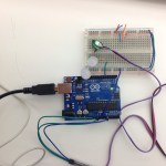
Pulse Sensor HW
Working: Problems: It does not seem to be reliable? It is pulsing with my pulse…
-

Ideas / Final Project
EEG reader / Processing and the Brain Basic Hack:
-
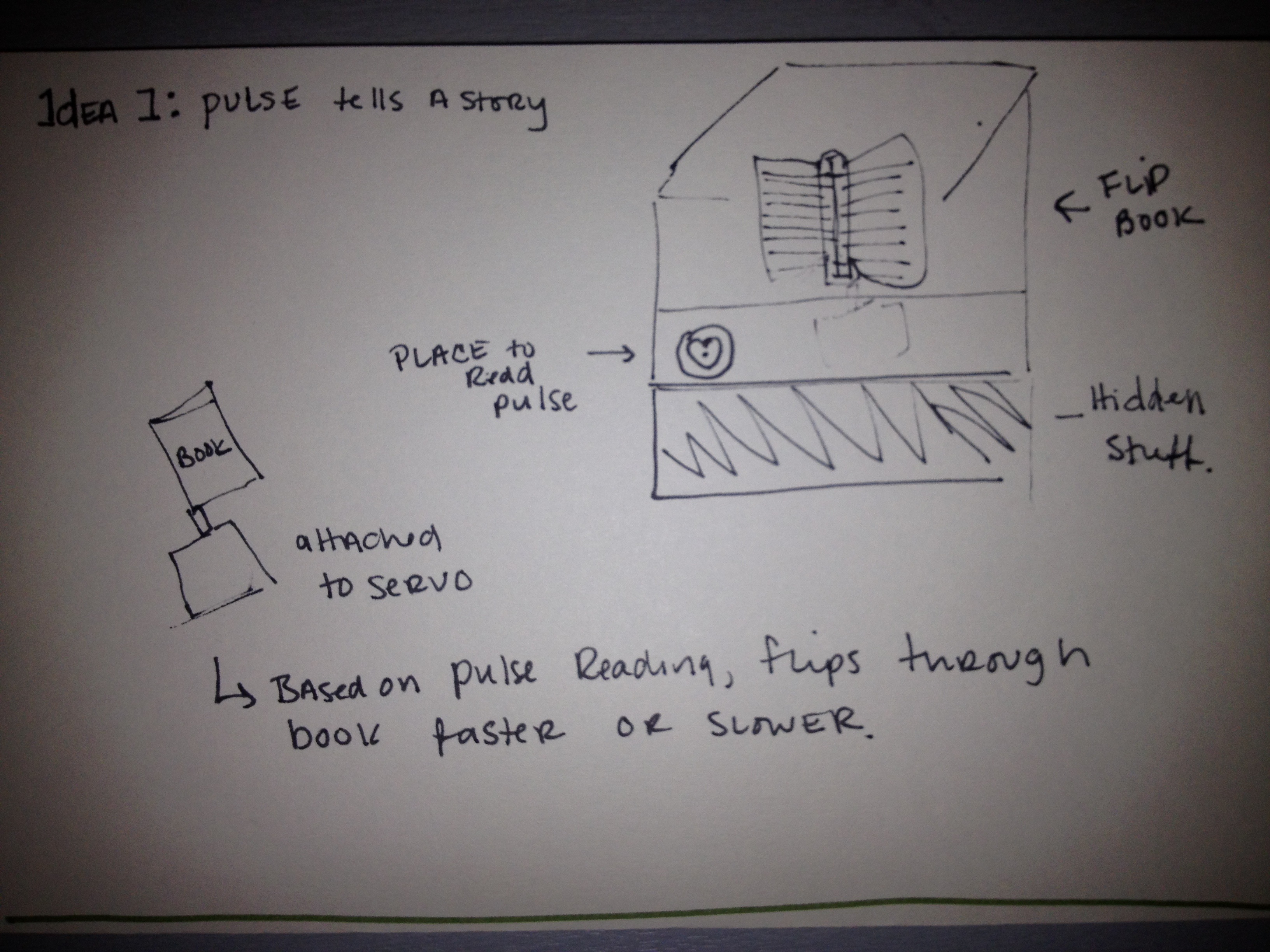
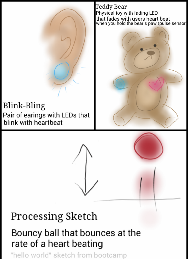
Big Ideas: Pulse Sensor
Here are my big ideas: 1. Flip Book 2. Film Reel: 3. Nervous Utensil
-

-
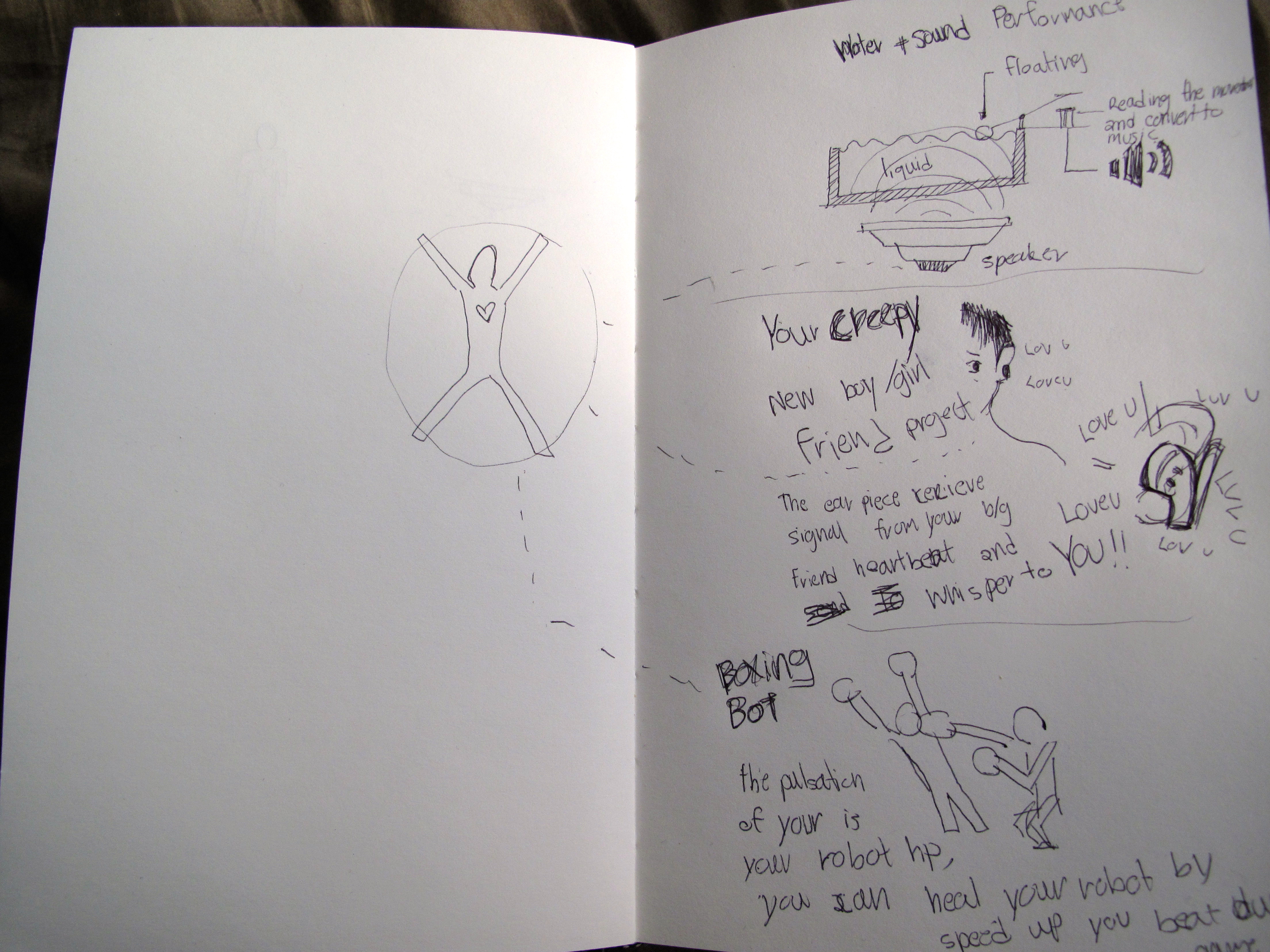
Simon / Pulse Sensor
Simon Pulse Sensor – idea 1. Water + Sound performance 2. Your creepy b/g friend…
-
PComp schedule for rest of 2012
Week 13 (Nov 30) Pulse Sensor Homework Setup Pulse Sensor to Blink 2 LED’s Week 14 …
-
[idea]
For the Pulse Sensor Project I want to use the values that I get to change…
-

Pulse Sensor
Idea One which is the traffic light is a tool for the gym. It has clearly…
-
Wireless and Wireless Pulse Sensor
1) To hook-up our RX and TX modules, read the KLP Walkthrough Tutorial pin read-out and…
-

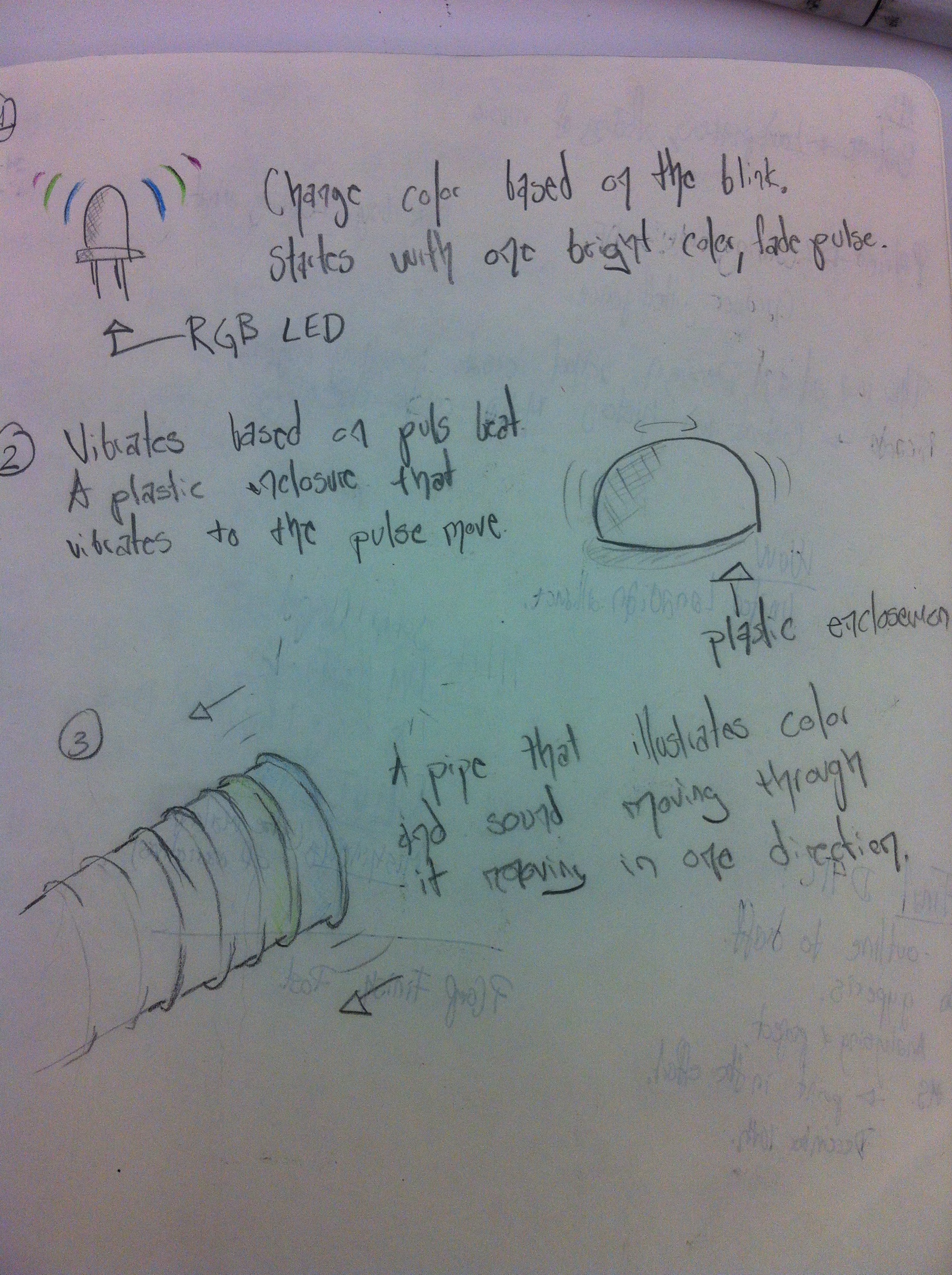
Pulse Sensor Project Ideas
Heart beat triggers a micro vibration motor inside of a stuffed frog and causes the frog…
-

-
Code and Ideas
Here a link to my case statments https://github.com/Sussesj/CC-LAB/tree/master/CaseStatment A video for it here: https://github.com/Sussesj/CC-LAB/blob/master/CaseStatments.mov And…
-
One Chip Many Programs
Using as DIP switch like below is common/traditional way to active/deactivate different programs or features on…
-

-

Sound Performance Toy
video: Here Code is Collapsed Here: [sourcecode collapse=”true”] <pre>int speakerPin= 7; int ledPin = 5; int…
-

Arduino Sound & Light Tool
Download the code here ›
You must be logged in to post a comment.