Updates from February, 2009 Toggle Comment Threads | Keyboard Shortcuts

  • Unknown's avatar

    Yury Gitman 8:42 pm on February 18, 2009 Permalink | Reply  

    Online Timepieces 

    Here are two time-based pieces that I found online

    Polar Clock (http://http://blog.pixelbreaker.com/polarclock/)
    Polar clock is a flash-based clock available as both a screensaver and a web app. While seemingly simple, this clock offers a wealth of information in a compact package, and is both organic and geometric at the same time. As you can see from the site, the clock has gone through several iterations of design, with the latest version (3.0) allowing for full customization by the user.

    BeatBearing (http://petes-sonic-art-research.blogspot.com/)

    Created for a PhD program in Belfast, BeatBearing is a time-based audio sequencer using ball bearings in a physical interface to interact with different musical samples. I can explain more but the video explains a lot.

    http://vimeo.com/moogaloop.swf?clip_id=2991443&server=vimeo.com&show_title=1&show_byline=1&show_portrait=0&color=&fullscreen=1
    BeatBearing Interview with Peter Bennett from Gus Sutherland on Vimeo.

     
  • Unknown's avatar

    Yury Gitman 8:32 pm on February 18, 2009 Permalink | Reply  

    Toy Fair 2009 

    The toy fair was huge and awesome. I got kicked out of a few booths, let into a few others, and talked to a lot of really interesting people (for the most part..). Here are some of the coolest things I saw:

    Cloud-B
    Cloud-B creates digital plush/plastic toys that aid children in falling asleep. Some of their products include “Dozy Dolphin” (interactive sounds/sleep sounds), “Sleep Sheep” (sleeping sounds), and “Twilight Turtle”(displays stars on walls of room through its shell). Here is a photo of the Twilight Turtle:

    Hex Bugs (http://www.hexbug.com)

    These guys were set up in the youth electronics section, were super friendly, and had AWESOME little robot bugs with a crapload of sensors in them like light, motion, infared, touch, direction, etc. Their site explains things very well, but here is a video I found online of the bugs in action (actually shot at the toy fair).

     
  • Unknown's avatar

    Yury Gitman 5:53 pm on February 18, 2009 Permalink | Reply  

    Time Based Art Works — Library 

    Joseph Beuys is a political artist He was a German fighter pilot in WWII and his plane was shot down in the middle of a snow storm in Crimea. A group of Tartar natives nursed him back to health with traditional folk remedies, that included wrapping him in animal fat for warmth. Beuys viewed this event as a rebirth and related his wounds to that of society's state.
    One of his projects that I found interesting was titled " I Like America and America Likes Me," 1974. For this piece, he wrapped himself in felt, representing a shepard, and locked himself in a cage converted gallery with a wild coyote for a week. Beuys would poke and prod the animal and a time-based recording of a turbine engine would roar through the room. Once the animal's growling grew fierce, Beuys would symbolize defeat by laying on the floor. The coyote never attacked Beuys and the animal was said to achieve "moral consciousness."

    Beuys


    Art on the Edge and Over
    , Linda Weintraub. p. 178 – 183. Art Insights, Inc. 1996.

    Another work that was based on time was that of Jan Dibbets, titled "Shortest Day at Konrad Fisher's Gallery," 1972. For this piece Dibbets photographed the same same detail of the Galerie Ficsher with the same perspective under different light conditions. He then mounted the individual photographs in chronological order on a large card. Displaying the photographs in this manner blurs the line of individuality and the viewer is forced to view them as a whole and change over time becomes prevelant.

    Dibbets

    Conceptual Art. Daniel Marzona. p. 54 -55. Taschen. 2005.

     
  • Unknown's avatar

    Yury Gitman 5:11 pm on February 18, 2009 Permalink | Reply  

    At Toy Fair 2009 

    The Toy Fair was fun and interesting. There were lots of interesting toys but not too many hi-tech ones which I was hoping to see. Here's a couple of toys that I found interesting:

    BluPLAY – A digital handheld art studio!

    Photo 59

    This is a portable electronic touch screen art studio that allows children to paint freely on a blank screen or on a coloring page. This seems like the perfect toy for children and includes music playing capabilities,  although it isn't ready to be hooked up to a computer yet. BluePixo had a single prototype on display which has a PIC32 chip under the hood. Joe and me had a long conversation with the creator of this toy. He apparently started working on this product in May 2008 which seems like a short time to have a prototype and a patent. I can see this toy being really popular if the retail price would be lesser than $60 a piece.

    SPYKEE – the spy robot

    Photo 60
    Photo 62

    This WiFi robot can be controlled with your computer from anywhere in the world. Besides moving about and looking cool it can take pictures, record video and be programmed to do really tiny things like changing channels on your television. The reamining Spykee range of robots are 3 smaller robots that are made for your ipod and can be controlled by Bluetooth or voice. There's a lot of ipod holding gizmos out there but none that look like a cool robot you can ask to change a song. I wouldn't mind owning one of these.

    Oh! I also made a new friend who told me something very funny about Joe and Nick.

    IMG_0887
     
  • Unknown's avatar

    Yury Gitman 4:27 pm on February 18, 2009 Permalink | Reply  

    Passage of time v0.1 

    Here’s my second iteration of the time piece. This prototype is a much higher fidelity and uses a tallish container I got from the container store. I’m using the container upside down with a hole cut at the bottom end for the USB cable and the Arduino stuck on the lid of the container. The LED’s are mounted around a tall cardboard structure, in 3 rows, which sits tight once stuck inside the container. The LED’s light up one row at a time and the light appears to move up and down the container. Row 1 and 3 are blue LED’s while row 2 is green LED’s. Kitchen towels doubled and nicely tucked into the container are used to diffuse the light.

    Photo 55

    Photo 45

    Photo 48

    Photo 49

    Photo 50

    Photo 51

    Photo 52

    Photo 54


    Photo 41

    Photo 43

    http://vimeo.com/moogaloop.swf?clip_id=3272939&server=vimeo.com&show_title=0&show_byline=0&show_portrait=0&color=00adef&fullscreen=1
    CODE:

    int timer = 50; // The higher the number, the slower the timing.
    int pins[] = { 2, 3, 4, 5, 6, 7, 8, 9, 10, 11, 12, 13 }; // an array of pin numbers
    int num_pins = 12; // the number of pins (i.e. the length of the array)
    int timer2 = 1000;
    void setup()
    {
    int i;
    for (i = 0; i < num_pins; i++) // the array elements are numbered from 0 to num_pins – 1
    pinMode(pins[i], OUTPUT); // set each pin as an output
    }
    void loop()
    {
    int i;
    //down up
    //bottom row
    for (i = 8; i < 12; i++) { // loop through each pin…
    digitalWrite(pins[i], HIGH); // turning it on,
    //delay(timer); // pausing,
    //digitalWrite(pins[i], LOW); // and turning it off.
    }
    delay(timer);
    for (i = 8; i < 12; i++) { // loop through each pin…
    //digitalWrite(pins[i], HIGH); // turning it on,
    //delay(timer); // pausing,
    digitalWrite(pins[i], LOW); // and turning it off.
    }
    delay(timer);
    //
    for (i = 4; i < 8; i++) { // loop through each pin…
    digitalWrite(pins[i], HIGH); // turning it on,
    //delay(timer); // pausing,
    //digitalWrite(pins[i], LOW); // and turning it off.
    }
    delay(timer);
    for (i = 4; i < 8; i++) { // loop through each pin…
    //digitalWrite(pins[i], HIGH); // turning it on,
    //delay(timer); // pausing,
    digitalWrite(pins[i], LOW); // and turning it off.
    }
    delay(timer);
    //
    for (i = 0; i < 4; i++) { // loop through each pin…
    digitalWrite(pins[i], HIGH); // turning it on,
    //delay(timer); // pausing,
    //digitalWrite(pins[i], LOW); // and turning it off.
    }
    delay(timer);
    for (i = 0; i < 4; i++) { // loop through each pin…
    //digitalWrite(pins[i], HIGH); // turning it on,
    //delay(timer); // pausing,
    digitalWrite(pins[i], LOW); // and turning it off.
    }
    delay(timer);
    //up down
    //
    for (i = 0; i < 4; i++) { // loop through each pin…
    digitalWrite(pins[i], HIGH); // turning it on,
    //delay(timer); // pausing,
    //digitalWrite(pins[i], LOW); // and turning it off.
    }
    delay(timer);
    for (i = 0; i < 4; i++) { // loop through each pin…
    //digitalWrite(pins[i], HIGH); // turning it on,
    //delay(timer); // pausing,
    digitalWrite(pins[i], LOW); // and turning it off.
    }
    delay(timer);
    //
    for (i = 4; i < 8; i++) { // loop through each pin…
    digitalWrite(pins[i], HIGH); // turning it on,
    //delay(timer); // pausing,
    //digitalWrite(pins[i], LOW); // and turning it off.
    }
    delay(timer);
    for (i = 4; i < 8; i++) { // loop through each pin…
    //digitalWrite(pins[i], HIGH); // turning it on,
    //delay(timer); // pausing,
    digitalWrite(pins[i], LOW); // and turning it off.
    }
    delay(timer);
    //bottom row
    for (i = 8; i < 12; i++) { // loop through each pin…
    digitalWrite(pins[i], HIGH); // turning it on,
    //delay(timer); // pausing,
    //digitalWrite(pins[i], LOW); // and turning it off.
    }
    delay(timer);
    for (i = 8; i < 12; i++) { // loop through each pin…
    //digitalWrite(pins[i], HIGH); // turning it on,
    //delay(timer); // pausing,
    digitalWrite(pins[i], LOW); // and turning it off.
    }
    delay(timer2);
    }

     
  • Unknown's avatar

    Yury Gitman 7:17 am on February 18, 2009 Permalink | Reply  

    international toy fair 2009. 

    just putting these down; i will add  mmore later.

    1. Snap Circuits. Brilliant learning tool for constructing simple electronic circuits. Joel Murphy should teach from this.  kits were cheap – less than $30 to build your own AM/FM radio or power a clock using a photocell. brilliant. probably my favorite product from the entire fair (except pillow toys).  If you want to build more advanced    things i think the most expensive kit which comes with A LOT of pieces was around $60. sooo cool. i want i want.IMG_0427

    2. Mattel's MindFlex.  Essentially allowing for telekinesis (using your mind to move objects) the user wears an apparatus on their head and controlls a ball floating atop jets of air. 

    Mind_flex_mattel

    HERE  is a pretty good blog article with a video demo and explanation from a mattel rep. game will retail for $80 (pretty expensive, but dirt cheap considering the technology being employed) and will be available in fall of this year. When i asked a mattel rep at toy fair he said "definitely before holiday season of this year". 

    …and i also had an "exciting time" with a "special someone"

    IMG_0422

    i'll add more, also a link to some of the videos i took while there —

     
  • Unknown's avatar

    Yury Gitman 10:37 pm on February 17, 2009 Permalink | Reply  

    Toy Fair — Fav Toys 

    The toy fair was very large and overwhelming. It contained a bunch of dolls and lead-detecting guns for toys. There were not many toys in the electroncs/high tech category. But these are two toys that I enjoyed.

    Orbitwheels

    These guys were on the 2nd floor giving a demonstration of their roller blade inspired contraptions. They were wheelin n dealin, but it looked like it required quite a bit of skill, which I did not have. The foot pad also detached so they could be stowed flat, and fit easily inside a book bag. The guy giving the demonstration was weaving his legs and it reminded me of a snake. Not sure how far you could get in these things, but they looked fun, at least for playing around.

    They also had a video of this crazy water skipper. You can check out more of their stuff on their site. (At the toy fair there was  a video of a guy wearing a suit, that rides this thing and casually dismounts onto a dock).
    http://www.inventist.com/.

    USB Controlled Cars

    UsbCars

    These cones are powered by a usb port. Once you plug them in, they light up and the little man waves. Arranging them in certain ways, dictates the direction of wireless cars that accompany the toy. However, they did not have a brochure for this toy (or that's what they told me), so I only have this pic from my iPhone which, unfortunately, does not show the car. I like the idea that this toy is powered by usb, but this requires that a usb connection be present. Their site is http://www.wizland.co.jp.  I couldn't find this toy on their site.

    I also found a date.

    Lego_Date

     
  • Unknown's avatar

    Yury Gitman 9:28 pm on February 16, 2009 Permalink | Reply  

    TED: Talks David Merrill: Siftables, the toy blocks that think 

    The future toy? Very interesting talk.

    http://www.ted.com/talks/david_merrill_demos_siftables_the_smart_blocks.html

     
    • Kirsten Halterman's avatar

      Kirsten Halterman 2:43 pm on February 17, 2009 Permalink | Reply

      Those are sooo cool – I want some! 🙂

  • Unknown's avatar

    Yury Gitman 12:47 am on February 14, 2009 Permalink | Reply  

    :::Prototype 1::: 

    Continuing with the idea of the grid as a way to show the progression of time, I came up with this little ghost character. The idea is that the light in his belly is stuff that he has eaten and you can see it go down as the lights move from his mouth (  I still have to give him a mouth) to his belly. I am still working on the code. It is taking me a bit to figure out how to create the progression of lights moving down. Since I really like the translucency of velum paper, I have made him out of it. In the inside there is the grid with light blue paper in front of it in the shape of a simplify digestive system, but it does not show 😦

    ::Sketch of character::
    Sketch

    ::ghost character::
    Front


    ::view from the top of the character::
    Inside 

    ::video:: 


    Notice that the code does not do what it should yet. Eventually a path of LEDs will light up at the top (mouth) and go down to its stomach. The LEDs at the "bottom of the stomach will stay lit. Eventually all the red LEDs will be lit up to show that its tummy is full and the cycle will be again.
    Another idea to show the passage of time would give him cheeks that light up in a circle like pattern to show the passage of time.


    ::Breadboard with very simple circuit::

    Breadboard

    :::Code::: It is just a variation of the Loop code but with more outputs

    int timer = 500;                   // The higher the number, the slower the timing.

    int pins[] = { 2, 3, 4, 5, 6, 7, 8, 9, 10, 11, 12, 13 }; // an array of pin numbers

    int num_pins = 12;                  // the number of pins (i.e. the length of the array)

    void setup()

    {

      int i;

      for (i = 0; i < num_pins; i++)   // the array elements are numbered from 0 to num_pins – 1

        pinMode(pins[i], OUTPUT);      // set each pin as an output

    }

    void loop()

    {

      int i;

      for (i = 0; i < num_pins; i++) { // loop through each pin…

        digitalWrite(pins[i], HIGH);   // turning it on,

        delay(timer);                  // pausing,

        digitalWrite(pins[i], LOW);    // and turning it off.

      }

      for (i = num_pins – 1; i >= 0; i–) { 

        digitalWrite(pins[i], HIGH);

        delay(timer);

        digitalWrite(pins[i], LOW);

      }

    }

     
  • Unknown's avatar

    Yury Gitman 3:07 pm on February 13, 2009 Permalink | Reply  

    Second Iteration: Cocoon 

     Klee003IMG_4072

    IMG_4077

    Code:

    void setup();
    void loop();
    int timer = 500;                   // The higher the number, the slower the timing.
    int pins[] = { 5, 7, 8, 10 }; //  pin numbers
    int num_rows = 4;                  // the number of pins

    void setup()
    {
      int i;

      for (i = 0; i < num_rows; i++)   // the array elements are numbered from 0 to num_pins – 1
        pinMode(pins[i], OUTPUT);      // set each pin as an output
    }

    void loop()
    {
      digitalWrite(pins[0], HIGH);
      digitalWrite(pins[1], HIGH);
      digitalWrite(pins[2], HIGH);
      digitalWrite(pins[3], HIGH);
     
      delay(2000);
     
      int i;
      int j;
      int height = 4;
     
       for (i = 0; i < num_rows; i++) { // loop through each row…
         digitalWrite(pins[i], LOW);
         delay(timer);
         for (j = height; j > 0; j–) {
           digitalWrite(pins[i], HIGH);   
           delay(timer);
           digitalWrite(pins[i], LOW);
           delay(timer);
         }
         height–;
         delay(timer);
       }

    }

     
  • Unknown's avatar

    Yury Gitman 3:05 pm on February 10, 2009 Permalink | Reply  

    :::prototype 1::: 

    The idea for the first prototype was to create a grid made out of 9 red LEDs and 3 white ones. The cycle of time would be of 30 seconds. Each white LED would lit up every 10 sec and the red ones would count up from 1-9 every time. The code it is not working the way I envisioned yet . This is the first iteration of the first prototype. The grid of LED's is mounted on hard velum paper and placed inside a box also made of velum. The velum provides for a nice diffuse light from the LEDs.

    ::Front view of box with LEDs inside on a grid::

    Photo 6

    ::Back view of the grid::

    Photo 7

    I utilized clay to keep the LEDs in place. I will use hot glue once I figure out what is the best arrangement for the LEDs

     
  • Unknown's avatar

    Yury Gitman 1:38 pm on February 10, 2009 Permalink | Reply  

    Prototype I – Time :: Kirsten Halterman 

    In exploring the passage of time, I created a pyramid using different colored LEDs. The pyramid grows from bottom to top with first the orange LEDs, then the green LEDs, and finally, the blue LEDs. Initially, I placed the blue LEDs on the bottom followed by the orange and then red LEDs. After testing, however, I discovered that the brightest LEDs were the blue ones. So, for a more dramatic effect, I placed them on the top. After reaching the top of the pyramid, the blue LEDs blink three times before decending down the pyramid.

    The top most point of the pyramid is connected to the “1” hole on the Arduino – this keeps it lit at all times.

    Because my experience with code is somewhat limited, I "faked" the speed of the lights to visually make it seem like the rows were blinking together. For example, the two orange LEDs at the bottom of the pyramid are blinking one after another but the speed at which they are blinking make them appear as if it were the same time.

    My sketch:

    Sketch

    Working Photo:

    MakingHole

    Photo of Board, Arduino & Photo of Project in Enclosure:

    Prototype1Photo

    Code

    Three weeks ago, I'd never heard of an arduino or breadboard – much less played around with them. This first project gave me some initial exposure and I enjoyed playing around with the code, breadboard, and arduino. My project is incredibly simple but I’m excited about learning more!

     
  • Unknown's avatar

    Yury Gitman 11:52 am on February 10, 2009 Permalink | Reply  

    Time – The dying arrow 

    SketchesArrow1SketchesArrow2

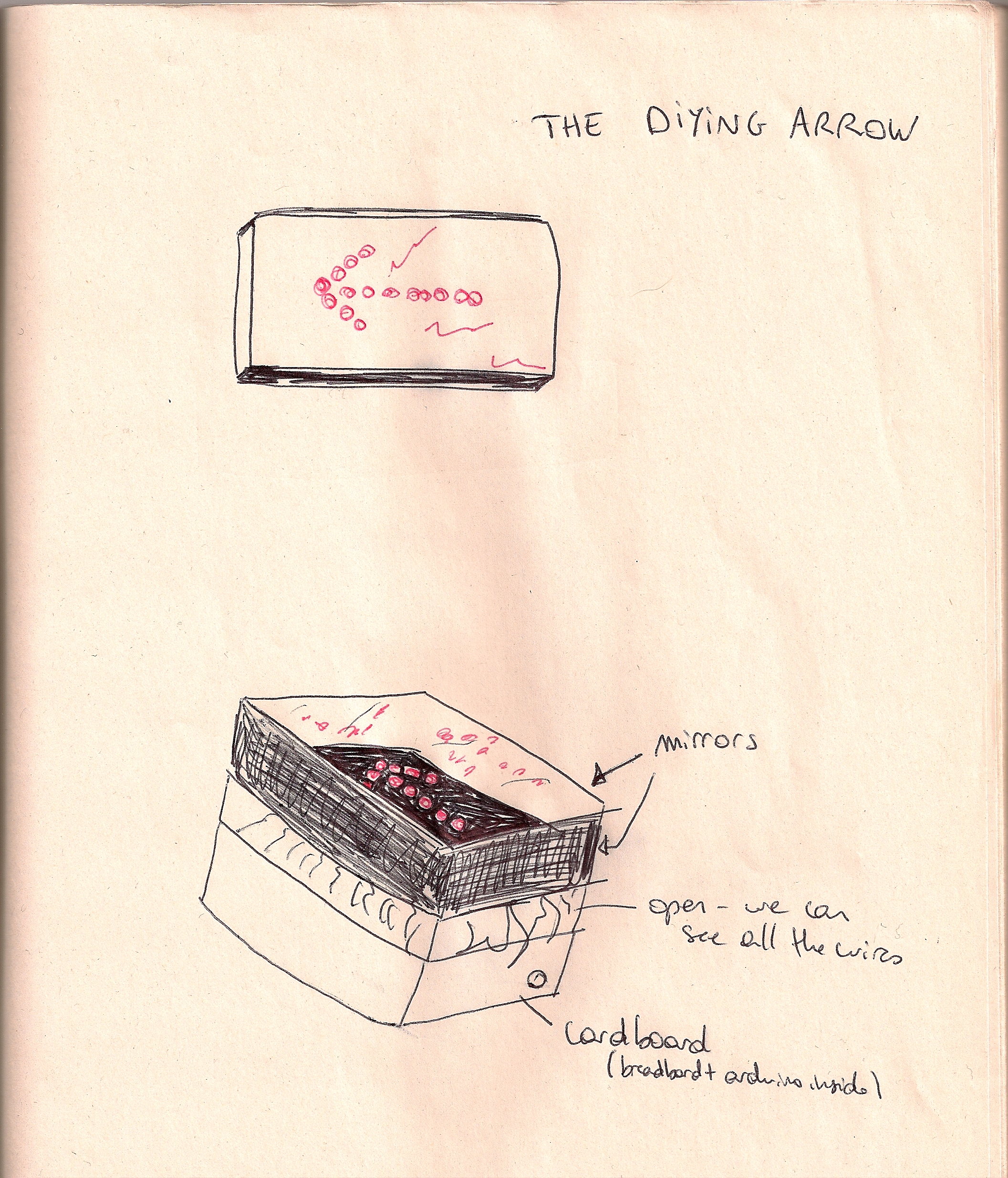
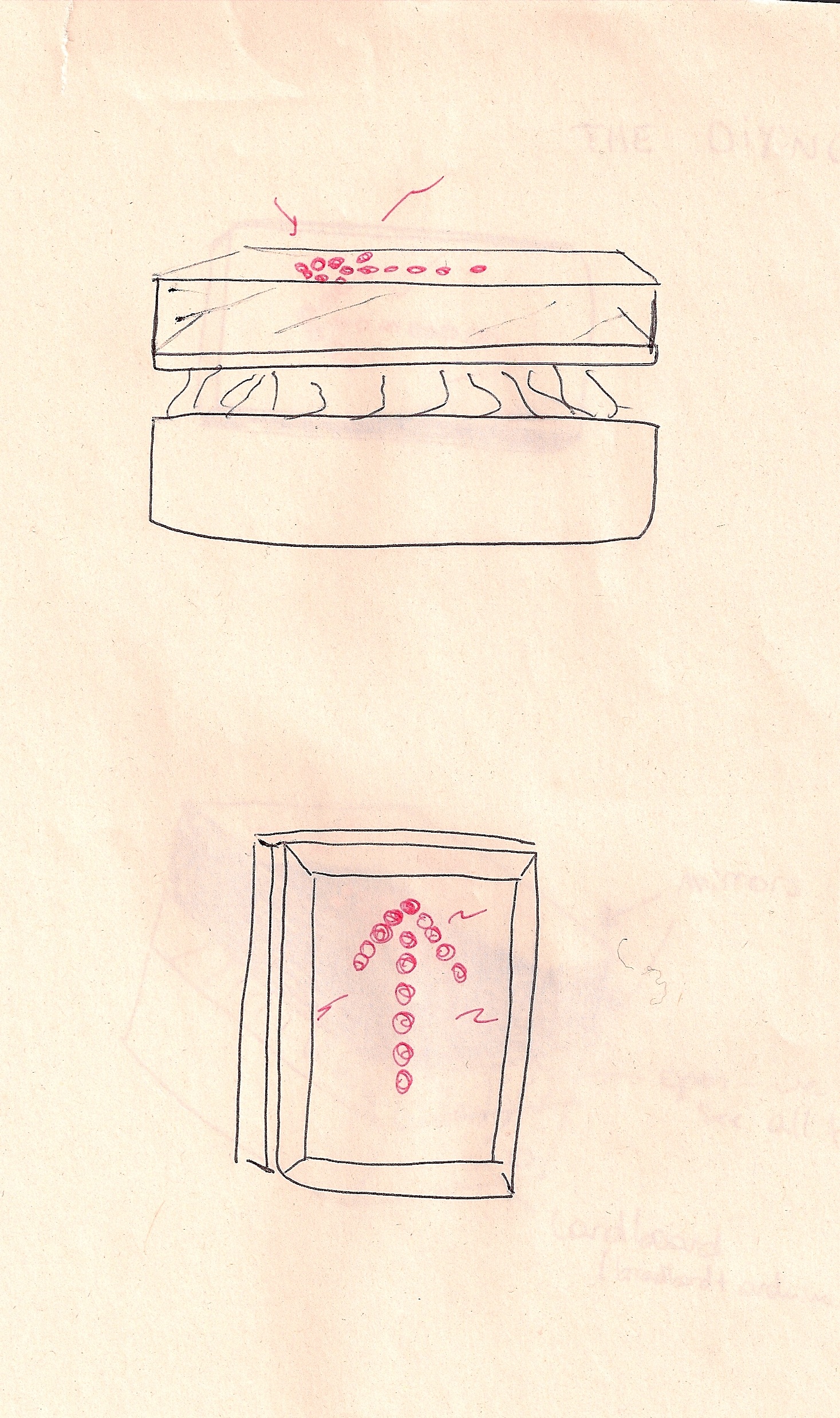
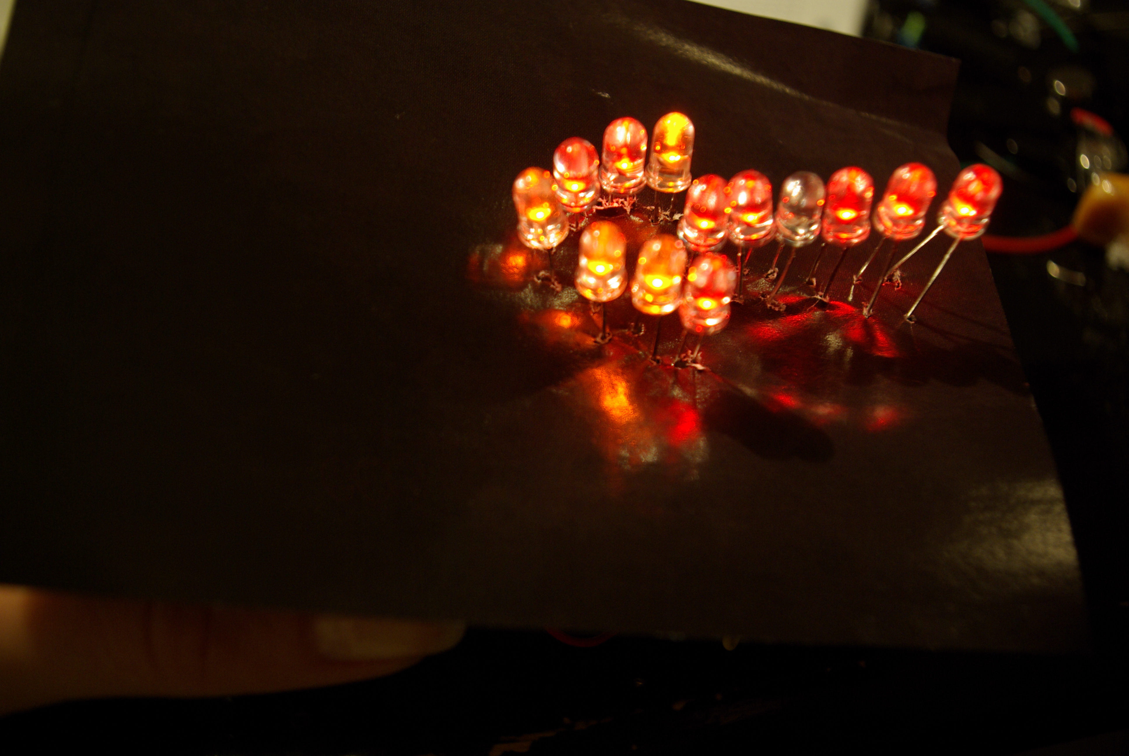
    The dying arrow is a project made of red and orange LEDs, that are all HIGH , and then turn one to one LOW. Such as a neon symbol not functioning well in bars, the "dying arrow" shows the passage of time where life goes off.
    _G105459

    _G105466  _G105467  _G105469

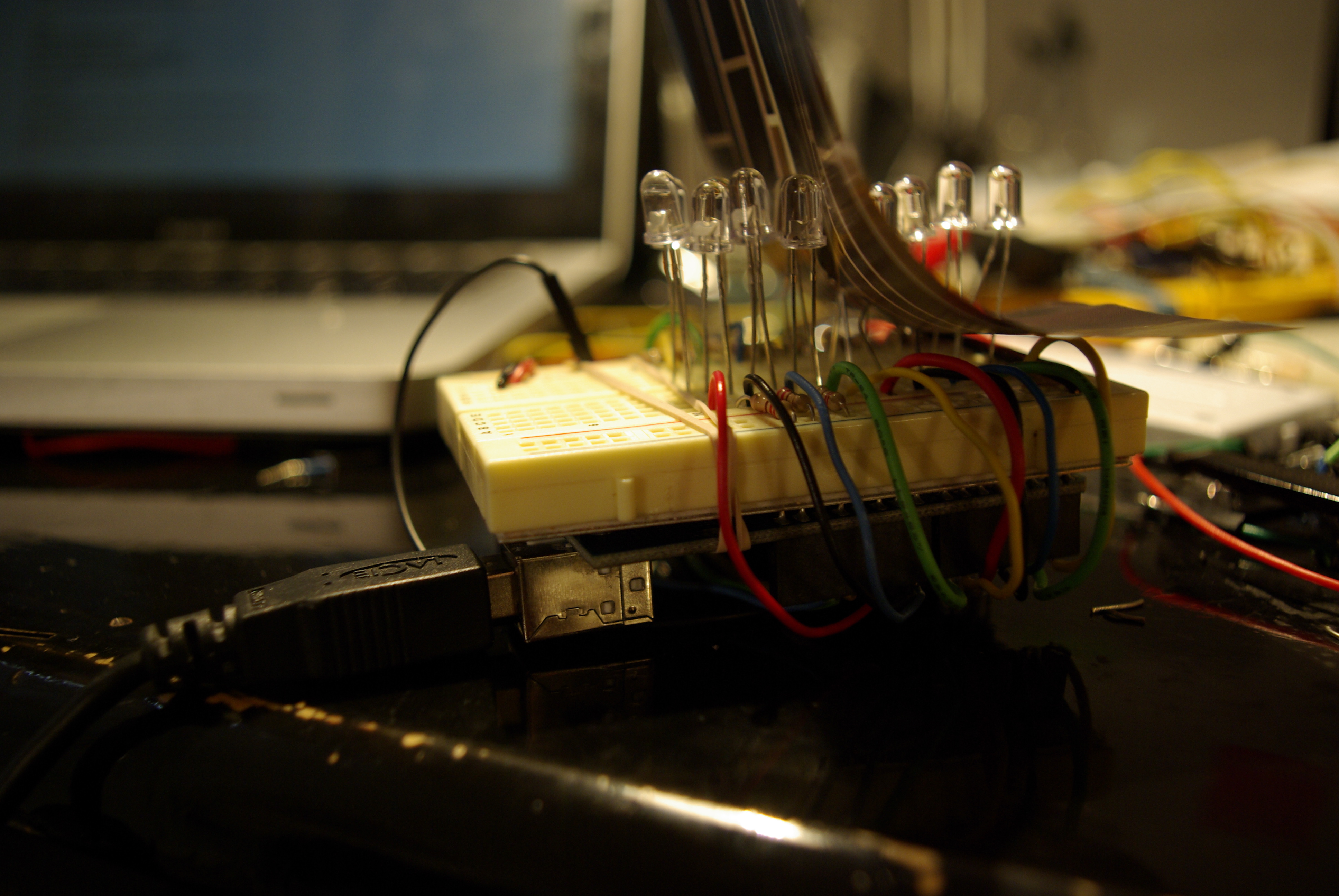
    I really enjoyed the rough aspect of my prototype, where you can see the wire, as well as the reflection of the red LEDs on the shiny black paper.
    I want my piece to preserve a rough aspect as a mechanism of the old times, and I will put mirrors around it to enhance its life and death.
    I had a hard time trying several possibilities in my code. It is not finished yet, and need to work on it a lot more! But it shows all the LEDs on HIGH with two of them blinking.
    I didn't use arrays because I couldn't get it working as I wanted.
    /* Myriam Aboukhater – code for the "Dying Arrow"

    13 LEDs are on HIGH at first, then they blink and pass on LOW one at a time
    */
    int Pin1 = 1;
    int Pin2 = 2;
    int Pin3 = 3;
    int Pin4 = 4;
    int Pin5 = 5;
    int Pin6 = 6;
    int Pin7 = 7;
    int Pin8 = 8;
    int Pin9 = 9;
    int Pin10 = 10;
    int Pin11 = 11;
    int Pin12 = 12;
    int Pin13 = 13;
    int value = HIGH;                // previous value of the LED

    long previousMillis = 0;        // will store last time LED was updated
    long interval = 1000;           // interval at which to blink (milliseconds)
    void setup()
    {
      pinMode (Pin1, OUTPUT);
      pinMode (Pin2, OUTPUT);
      pinMode (Pin3, OUTPUT);
      pinMode (Pin4, OUTPUT);
      pinMode (Pin5, OUTPUT);
      pinMode (Pin6, OUTPUT);
      pinMode (Pin7, OUTPUT);
      pinMode (Pin8, OUTPUT);
      pinMode (Pin9, OUTPUT);
      pinMode (Pin10, OUTPUT);
      pinMode (Pin11, OUTPUT);
      pinMode (Pin12, OUTPUT);
      pinMode (Pin13, OUTPUT);  
    }

    void loop()
    {
      digitalWrite (Pin1, HIGH);
      digitalWrite (Pin2, HIGH);
      digitalWrite (Pin3, HIGH);
      digitalWrite (Pin4, HIGH);
      digitalWrite (Pin5, HIGH);
      digitalWrite (Pin6, HIGH);
      digitalWrite (Pin7, HIGH);
      digitalWrite (Pin8, HIGH);
      digitalWrite (Pin9, HIGH);
      digitalWrite (Pin10, HIGH);
      digitalWrite (Pin11, HIGH);
      digitalWrite (Pin12, HIGH);
      digitalWrite (Pin13, HIGH);

      // if (millis() – previousMillis > interval) {
        //previousMillis = millis();   // remember the last time we blinked the LED

      
        if (value == HIGH) {
         digitalWrite(Pin3, LOW);   // sets the LED on
          delay(70);                  // waits for a second
          digitalWrite(Pin3, HIGH);    // sets the LED off
          delay(70);                  // waits for a second
          
          digitalWrite(Pin7, LOW);   // sets the LED on
          delay(10);                  // waits for a second
          digitalWrite(Pin7, HIGH);    // sets the LED off
          delay(10);                  
        }    
         
      }
        }


  • Unknown's avatar

    Yury Gitman 9:07 am on February 10, 2009 Permalink | Reply  

    Passage of Time / Ira Goldberg 

    My passage of time is a sheep counting night lamp. The idea is to visualize the sheep counting action and use the lights as another way to fall asleep. I used colored and white paper in which I made holes in different patterns. 

    Sketch 

    Pic

     
    http://vimeo.com/moogaloop.swf?clip_id=3157124&server=vimeo.com&show_title=1&show_byline=1&show_portrait=0&color=&fullscreen=1
    Sheep Counting from Ira Goldberg on Vimeo.

     
  • Unknown's avatar

    Yury Gitman 5:21 am on February 10, 2009 Permalink | Reply  

    Time Piece from [far & old] East 

    DSC_3042

    DSC_3020

      Okay so originally I did a time piece using LEDs in hour glass formation shown above….but then I got kinda bored with the thing. 

      I remembered  when I took a trip to Vietnam many summers ago I heard someone chiming a symbol and stroking a drum in the middle of the night!….I found out that the sound was the village time keeper anouncing the time in Chinese zodiac notation. So hear is my ode to mr. one-man-band, batteries included, chime man time keeper guy.

    This rough is prototype v1.5.  The next version will have all 12 animals & represent the passing of one full day - ancient analog – digital mash up style. 

    DSC_3052

    dragon cometh [1976, 1988 by the by]

    DSC_3055

    "there…Grrrrreat…."

    DSC_3056

    "silly wabbit PIC-Chips are for are for kids" (jp i like pic chips too)

     DSC_3065

    party like an animal!


    Cheers!

     
    • Linhda Le's avatar

      Linhda Le 3:00 am on February 11, 2009 Permalink | Reply

      That’s kind of cool!!

  • Unknown's avatar

    Yury Gitman 2:22 am on February 10, 2009 Permalink | Reply  

    Time based Arduino/LEDs 

    Second prototype of the Arduino LED time piece. This time is much
    higher fidelity. I got some nice clear round enclosures from the
    container store, and customized them to created a really nice feeling
    container for the project. I used a dremel tool to create openings for
    power and USB, and sanded the lid down to create a nice diffusing
    effect. Inside the enclosure, I have an array of 12 LEDs in a circular
    pattern, grounded in series and connected to power pins on the Arduino
    individually. They are connected using wire-wrapping and hot glue. I am diffusing them further through two more layers of plastic and some paper, however the effect is minimal at best. I think I need a taller container or need to work with more LEDs (possibly 2 per pin?) to create a more uniform circular shape like I want. You can see the various ways that
    I programmed it in the video (if there is no video i’m waiting on Vimeo to upload it and it’ll be up shortly…be patient please!)

    http://vimeo.com/moogaloop.swf?clip_id=3156703&server=vimeo.com&show_title=1&show_byline=1&show_portrait=0&color=&fullscreen=1
    Arduino LED Time Prototype 2 from Steve Varga on Vimeo.

    Here’s the code:

    Download Prototype2_00

    Sketch
     

    Image2 Image1

    Image4

    Image5

    Image6

    Image7

     
  • Unknown's avatar

    Yury Gitman 11:03 pm on February 9, 2009 Permalink | Reply  

    LED Passage of Time – Prototype 2 

    Layout_2_web

    These are the sketches I made to map out how I wanted to make the prototype. I drilled holes for 13 leds and wire wrapped all of the legs and used a common ground.

    Here it is with a light pattern that does not include pwm.


    Arduino code.

     
  • Unknown's avatar

    Yury Gitman 8:48 pm on February 9, 2009 Permalink | Reply  

    LED time piece • v02 

    sorry i can't be in class today, but here now, for your enjoyment is my second iteration of the timepiece.

    schematic of the design i devised and then executed:

    LED_timepiece

    Here's a photo of the guts of the box; as you can see, the male header pins which have been wire-wrapped, and then hot glued fit quite nicely into the digital pins of the arduino:

    CIMG1340_cropped

    no need to compliment my superb wire organization skills. no, really.

    finally, here is the piece in action:

    CIMG1327_cropped

    I tried to arrange the LEDs in a pattern according to color (yes, believe it or not, they are not randomly spread out over the cardboard backbone you see up there).  My thought was that the color alone would express the progression of time, along with the incrementing light. I think the result would make a good entry into the failblog(.org).  i don't think it works well at all. Aesthetically, i am satisfied, and the sequence still comes through, but it doesn't have the same gravity as when the colors were placed together, in order.

    my hilariously ineffective code can be viewed HERE.  yes, i realized a nested for loop could accomplish the final 500 lines in about 10, but that's just my style, OK?! i'll fix this in the next iteration, most definitely.

    speaking of my next iteration, i realized after working on this project, that i am BASICALLY re-constructing the same object/aesthetic as i did for my studio final LAST SEMESTER.  a cube, littered with colored LEDs. see what the hell i am talking about.  i have decided that my next iteration will be a completely new enclosure, and will consist of a perfect sphere(s). i'm done with cubes, it will be a very, very long time before i put LEDs into plastic or plexi cubes. this i vow.

    a lot more images of the construction

    for some reason, vimeo is taking more than 200 minutes to 'convert' the vid. here is the link:

    http://vimeo.com/3156311

     
c
Compose new post
j
Next post/Next comment
k
Previous post/Previous comment
r
Reply
e
Edit
o
Show/Hide comments
t
Go to top
l
Go to login
h
Show/Hide help
shift + esc
Cancel