Updates from March, 2011 Toggle Comment Threads | Keyboard Shortcuts

  • Unknown's avatar

    hilalkoyuncu 6:58 pm on March 7, 2011 Permalink | Reply  

    Bathroom Psychic & Towel Spy 

    My devices were supposed to look a little different but I thought I could communicate the same idea with other alternatives.

    My  devices are the bathroom psychic who could tell by the (temperature, light and time) what kinds of activities are going on inside the bathroom. Both devices communicate the information with both visual and auditory feedback.

    The bathroom unit is the Towel Spy, he kind of “hangs” in the bathroom an keeps an eye on what’s going on.

    Both devices have buzzers. Additionally, the psychic has a push button  to set off the buzzer on the towel, this can be used if the user is in a hurry to get in the bathroom.  The buzzer on the psychic is an auditory feedback to let the user know that the bathroom  is vacant.

    I borrowed the facial expressions from Andy and Min Ho’s “fridge friends” since I didn’t have enough time to create the ones that I planned to have.

    Please watch the case study video and please do not make fun of my acting skills:)

    Grazie

    Bathroom Psychic—-


    Towel Spy——-

    http://vimeo.com/20753191

    Vimeo is being crazy so here is a youtube link:


  • Unknown's avatar

    Lee 2:53 pm on March 7, 2011 Permalink | Reply  

    Bathroom Monitor – Lee 

    So this project is more of an exercise than a creative endeavor. I have 2 xbees, a couple photo resistors, LED’s and a servo. What can I make with that?

    I really focused in on the servo because it’s been in my toolkit for months and I’d yet to use it to actually make something move. This sparked the idea of analog public bathroom occupied signs. Now I know there’s no practical reason those switches should ever be replaced with digital wireless technology, that’s some crazy overkill, but the idea of making one of those analog style rollover signs seemed like an interesting exercise. I set about figuring out how something like that would work.

    First I looked into what kind of range my servo had because that would determine to a great extent the limitations of the design. The spec sheet says 90 degrees, but I found it could do about 110 degrees, I decided to split the difference and make my window 100 degrees.

    Next I choose an enclosure and measured the workable space I’d have and scaled my cutout window to it and then that determined how large the rotating sign could be. When the sign is vacant the hidden occupied portion needs to clear side and bottom of the enclosure.

    Now it was just a matter of building my circuits.

    At this point I decided to add some LED indicators as well in case the lights were off / could act as an ambient notification. It was time to test it out.

    and testing out the range.

    and my girlfriend though it was funny as well.

     
  • Unknown's avatar

    Bree 6:53 am on March 7, 2011 Permalink | Reply  

    Casing for the simple lights-on sensor 

    Here is a super simple casing for the “lights-on/off” sensor system for bathroom occupancy…

    I imagine it in a frat house somewhere.

     
  • Unknown's avatar

    Bree 6:34 am on March 7, 2011 Permalink | Reply  

    After working on the very simple premise of making a photo-resistor-dependent thingamagig, I seem to have killed my Xbee. I have NO idea how it happened, but Xctu can no longer talk to it :(.  I am at a loss as to what killed it, but I am suspecting my bad luck lately with these things.

    It might, of course, be his fault…


  • Unknown's avatar

    Behnaz Babazadeh 1:37 am on March 7, 2011 Permalink | Reply  

    Bathroom Occupancy Monitor 

    My roommate is always frustrated with the rest of us making it into the bathroom before she does. Here is a remote bathroom occupancy system that can keep her in bed and happy. By utilizing the romantic light sensor workshop from last week, I was able to achieve the wireless communication between my two Xbees. The router is in a soup container placed inside of the bathroom and the coordinator is in a box by her bed side with two icon lights that allow her to know if the person has left, is only using for 5 min or for longer (taking a shower).

    (More …)

     
  • Unknown's avatar

    lpercifield 11:22 pm on March 6, 2011 Permalink | Reply  

    Chapter 5: Simple Sensor Network 

    Download the processing sketch:

    Download the library:

    We will show you how to implement this library in class.

    There are two possible ways to build the circuit for tomorrows class:

    YOU CAN PICK WHICH SET OF PARTS YOU BRING
    Circuit 1 requires:
    YOU WILL NEED TO SUPPLY THESE PARTS!!
    3.3v power regulator
    10uF capacitor
    OR
    Circuit 2 requires:
    YOU WILL NEED TO SUPPLY THESE PARTS!
    All other parts will be supplied
    We will be making the following circuits in class:
     
  • Unknown's avatar

    andywallace 9:20 pm on March 6, 2011 Permalink | Reply  

    Christmas Intruder Alert 

    The Christmas Intruder Alert system is a wireless device lets parents know if their kids have been peeping in the present stash. A small egg is set up with the presents that is sensitive to light. When there is light, a remote unit will show that the space has been breached. This warning light will stay lit until it is reset by the parent.


    It’s that simple! And now you can know when your children are trying to spoil the magic of Christmas!

    (More …)

     
  • Unknown's avatar

    andywallace 8:47 pm on March 6, 2011 Permalink | Reply  

    Hostile Interaction Mediator & Doorbell 

    Proper write up by Thom Hines:  https://makingtoys.net/2011/03/03/hostile-interaction-mediator-doorbell/

     
  • Unknown's avatar

    Alvaro Soto 10:14 pm on March 3, 2011 Permalink | Reply  

    Traffic Light Doorbell 

    First time

    The first time anyone presses the button a green light turns On and plays a nice melody. This way the user will know the bell worked.

    Second Time

    Usually the bell is pressed twice after sometime waiting, this is Ok and the Doorbell will tell the user that it worked, but a warning color and tone will be given to the user.

    Third Time

    This is the final notice, the user will now have to wait 5 minutes until he/she can press the button and get a signal. (a warning red color and angry tone will be given to the user).

     
  • Unknown's avatar

    Oylum 10:10 pm on March 3, 2011 Permalink | Reply  

    Soak ’em Up 

    With this tool, no one will dare to annoy you by buzzing your doorbell for long…or no one will ever visit you again!


    Process

    Source Code for the Receiver

    
    #include <NewSoftSerial.h>
    NewSoftSerial mySerial(2,3);
    
    /*
    doorbell basic DINGY!!
    by Rob Faludi faluudi.com
    */
    
    #define VERSION "1.00a0"
    
    boolean dumpWater = false;
    int water = 7;
    
    long previousMillis = 0;
    long interval = 5000;
    int BUTTON = 5;
    int counter=0;
    
    void setup(){
      pinMode(water, OUTPUT);
      pinMode(BUTTON, INPUT);
      pinMode(13,OUTPUT);
      mySerial.begin(9600);
    }
    
    void loop(){
      //look for a capital D over the serial port and ring the bell if found
      unsigned long currentMillis = millis();
      if(currentMillis - previousMillis > interval&&dumpWater==true) {
        dumpWater=false;
        digitalWrite(water, LOW);
        digitalWrite(13, LOW);
      }
      if(counter>=300){
          previousMillis = currentMillis;
          dumpWater=true;
          digitalWrite(water, HIGH);
          digitalWrite(13, HIGH);
          counter=0;
      }
      if (mySerial.available() > 0){
        if (mySerial.read() == 'W') {
            //ring bell briefly
            previousMillis = currentMillis;
            dumpWater=true;
            digitalWrite(water, HIGH);
            digitalWrite(13, HIGH);
            delay(10);
            
          }
        }
        if (digitalRead(BUTTON) == HIGH){
         mySerial.print('R');
         counter++;
         //digitalWrite(13,HIGH);
         delay(10); //prevents overwhelming the serial port
        }
    }


    Source Code for the Sender Button

    
    #include <NewSoftSerial.h>
    
    /*
    doorbell basic BUTTON!!
    by Rob Faludi faluudi.com
    */
    NewSoftSerial mySerial(2,3);
    
    #define VERSION "1.00a0"
    boolean dumpWater=false;
    int BUTTON = 5;
    int resetButton = 8;
    int bell = 7;


    void setup(){
      pinMode(BUTTON, INPUT);
      pinMode(resetButton, INPUT);
      pinMode(bell, OUTPUT);
      pinMode(13,OUTPUT);
      mySerial.begin(9600);
    }
    
    void loop(){
      //send a capital D over the serial port if the button is pressed
      if(dumpWater==false){
        digitalWrite(13,HIGH);
      }else{
        digitalWrite(13,LOW);
      }
      if(digitalRead(resetButton)==HIGH && dumpWater==true){
        dumpWater=false;
      }
      if (digitalRead(BUTTON) == HIGH){
        if(dumpWater==false){
           mySerial.print('W');
           //digitalWrite(13,HIGH);
           delay(10); //prevents overwhelming the serial port
           dumpWater=true;
        }
      }
      if (mySerial.available() > 0&&dumpWater==false){
        if (mySerial.read() == 'R') {
            //ring bell briefly
            //previousMillis = currentMillis;
            //dumpWater=true;
            digitalWrite(bell, HIGH);
            //digitalWrite(13, HIGH);
            delay(10);
            digitalWrite(bell, LOW);
            
          }
        }
    }
    

    by Leif, Chris, Oylum

     
  • Unknown's avatar

    thisisvictorkim 9:56 pm on March 3, 2011 Permalink | Reply  

    Traffic Light Doorbell by Alvaro, Bree, and Victor 

    code for the doorbell buzzer and doorbell bell

    (More …)

     
  • Unknown's avatar

    Behnaz Babazadeh 9:36 pm on March 3, 2011 Permalink | Reply  

    Simon Package Delivery System 

    Look & Feel Presentation

    SIMON

     (More ...)
     
  • Unknown's avatar

    hilalkoyuncu 9:31 pm on March 3, 2011 Permalink | Reply  

    Romantic Lighting Sensor with Feedback(Exercise-2) 

    You keep the exact same wiring as the first exercise.

    • Additionally, you will add an LED to pin 19 of the Sensor Breadboard.


    • Configure your Router XBee:

    +++

    ATD14(To put pin 1 in low digital output mode, LED.)

    ATWR(To save the settings.)

    • Upload the second code that Kate posted to the base board Arduino.

    You will get this:

     
  • Unknown's avatar

    catherine 9:19 pm on March 3, 2011 Permalink | Reply  

    Code for Romantic Lighting with Feedback 

    Code needed for the second part of the lesson.

    /*
     * *********ROMANTIC LIGHTING SENSOR WITH FEEDBACK********
     * detects whether your lighting is
     * setting the right mood and shows
     * you the results on the sensor module
     * USES PREVIOUSLY PAIRED XBEE ZB RADIOS
     * by Rob Faludi http://faludi.com
     */
    
    /*
    *** CONFIGURATION ***
     
     SENDER: (REMOTE SENSOR RADIO)
     ATID3456 (PAN ID)
     ATDH -> set to SH of partner radio
     ATDL  -> set to SL of partner radio
     ATJV1 -> rejoin with coordinator on startup
     ATD02  pin 0 in analog in mode with a photo resistor (don't forget the voltage divider circuit--resistor to ground is good)
     ATD14  pin 1 in digital output (default low) mode with an LED from that pin to ground
     ATIR64 sample rate 100 millisecs (hex 64)
     
     
     * THE LOCAL RADIO _MUST_ BE IN API MODE *
     
     RECEIVER: (LOCAL RADIO)
     ATID3456 (PAN ID)
     ATDH -> set to SH of partner radio
     ATDL  -> set to SL of partner radio
     
     */
    
    #define VERSION "1.02"
    
    int LED = 11;
    int debugLED = 13;
    int analogValue = 0;
    int remoteIndicator = false; // keeps track of the desired remote on/off state
    int lastRemoteIndicator = false; // record of prior remote state
    unsigned long lastSent = 0; // records last time the remote was re-set to keep it in sync
    
    
    void setup() {
      pinMode(LED,OUTPUT);
      pinMode(debugLED,OUTPUT);
      Serial.begin(9600);
    }
    
    
    void loop() {
      // make sure everything we need is in the buffer
      if (Serial.available() >= 23) {
        // look for the start byte
        if (Serial.read() == 0x7E) {
          //blink debug LED to indicate when data is received
          digitalWrite(debugLED, HIGH);
          delay(10);
          digitalWrite(debugLED, LOW);
          // read the variables that we're not using out of the buffer
          // (includes two more for the digital pin report)
          for (int i = 0; i<20; i++) {
            byte discard = Serial.read();
          }
          int analogHigh = Serial.read();
          int analogLow = Serial.read();
          analogValue =  analogLow + (analogHigh * 256);
        }
      }
    
      /*
       * The values in this section will probably
       * need to be adjusted according to your
       * photoresistor, ambient lighting and tastes.
       * For example, if you find that the darkness 
       * threshold is too dim, change the 350 value
       * to a larger number.
       */
    
      // darkness is too creepy for romance
      if (analogValue > 0 && analogValue <= 350) {
        digitalWrite(LED, LOW);
        remoteIndicator = false;
      }
      // medium light is the perfect mood for romance
      if (analogValue > 350 && analogValue <= 750) {
        digitalWrite(LED, HIGH);
        remoteIndicator = true;
      }
      // bright light kills the romantic mood
      if (analogValue > 750 && analogValue <= 1023) {
        digitalWrite(LED, LOW);
        remoteIndicator = false;
      }
    
      // set the indicator immediately when there's a state change
      if (remoteIndicator != lastRemoteIndicator) {
        if (remoteIndicator==false) setRemoteState(0x4);
        if (remoteIndicator==true) setRemoteState(0x5);
        lastRemoteIndicator = remoteIndicator;
      }
    
      // re-set the indicator occasionally in case it's out of sync
      if (millis() - lastSent > 10000 ) {
        if (remoteIndicator==false) setRemoteState(0x4);
        if (remoteIndicator==true) setRemoteState(0x5);
        lastSent = millis();
      }
    
    
    }
    
    void setRemoteState(int value) {  // pass either a 0x4 or and 0x5 to turn the pin on or off
      Serial.print(0x7E, BYTE); // start byte
      Serial.print(0x0, BYTE); // high part of length (always zero)
      Serial.print(0x10, BYTE); // low part of length (the number of bytes that follow, not including checksum)
      Serial.print(0x17, BYTE); // 0x17 is a remote AT command
      Serial.print(0x0, BYTE); // frame id set to zero for no reply
      // ID of recipient, or use 0xFFFF for broadcast
      Serial.print(00, BYTE);
      Serial.print(00, BYTE);
      Serial.print(00, BYTE);
      Serial.print(00, BYTE);
      Serial.print(00, BYTE);
      Serial.print(00, BYTE);
      Serial.print(0xFF, BYTE); // 0xFF for broadcast
      Serial.print(0xFF, BYTE); // 0xFF for broadcast
      // 16 bit of recipient or 0xFFFE if unknown
      Serial.print(0xFF, BYTE);
      Serial.print(0xFE, BYTE);
      Serial.print(0x02, BYTE); // 0x02 to apply changes immediately on remote
      // command name in ASCII characters
      Serial.print('D', BYTE);
      Serial.print('1', BYTE);
      // command data in as many bytes as needed
      Serial.print(value, BYTE);
      // checksum is all bytes after length bytes
      long sum = 0x17 + 0xFF + 0xFF + 0xFF + 0xFE + 0x02 + 'D' + '1' + value;
      Serial.print( 0xFF - ( sum & 0xFF) , BYTE ); // calculate the proper checksum
      delay(10); // safety pause to avoid overwhelming the serial port (if this function is not implemented properly)
    }


  • Unknown's avatar

    catherine 9:14 pm on March 3, 2011 Permalink | Reply  

    Code for Romantic Light Sensor base station 

    PART ONE OF LESSON. COPY & PASTE THIS INTO ARDUINO FIRST.

    /*
     * *********ROMANTICLIGHTING SENSOR ********
     * detects whether your lighting is
     * setting the right mood
     * USES PREVIOUSLY PAIRED XBEE ZB RADIOS
     * by Rob Faludi http://faludi.com
     */
    
    /*
    *** CONFIGURATION ***
     
     SENDER: (REMOTE SENSOR RADIO)
     ATID3456 (PAN ID)
     ATDH -> set to SH of partner radio
     ATDL  -> set to SL of partner radio
     ATJV1 -> rejoin with coordinator on startup
     ATD02  pin 0 in analog in mode
     ATIR64 sample rate 100 millisecs (hex 64)
     
     
     * THE LOCAL RADIO _MUST_ BE IN API MODE *
     
     RECEIVER: (LOCAL RADIO)
     ATID3456 (PAN ID)
     ATDH -> set to SH of partner radio
     ATDL  -> set to SL of partner radio
     
     */
    
    #define VERSION "1.02"
    
    int LED = 11;
    int debugLED = 13;
    int analogValue = 0;
    
    
    void setup() {
      pinMode(LED,OUTPUT);
      pinMode(debugLED,OUTPUT);
      Serial.begin(9600);
    }
    
    
    void loop() {
      // make sure everything we need is in the buffer
      if (Serial.available() >= 21) {
        // look for the start byte
        if (Serial.read() == 0x7E) {
          //blink debug LED to indicate when data is received
          digitalWrite(debugLED, HIGH);
          delay(10);
          digitalWrite(debugLED, LOW);
          // read the variables that we're not using out of the buffer
          for (int i = 0; i<18; i++) {
            byte discard = Serial.read();
          }
          int analogHigh = Serial.read();
          int analogLow = Serial.read();
          analogValue =  analogLow + (analogHigh * 256);
        }
      }
    
      /*
       * The values in this section will probably
       * need to be adjusted according to your
       * photoresistor, ambient lighting and tastes.
       * For example, if you find that the darkness 
       * threshold is too dim, change the 350 value
       * to a larger number.
       */
    
      // darkness is too creepy for romance
      if (analogValue > 0 && analogValue <= 350) {
        digitalWrite(LED, LOW);
      }
      // medium light is the perfect mood for romance
      if (analogValue > 350 && analogValue <= 750) {
        digitalWrite(LED, HIGH);
      }
      // bright light kills the romantic mood
      if (analogValue > 750 && analogValue <= 1023) {
        digitalWrite(LED, LOW);
      }
    
    }
    
     
  • Unknown's avatar

    hilalkoyuncu 9:09 pm on March 3, 2011 Permalink | Reply  

    Romantic Lighting Sensor(Exercise 1) 

    “WIRELESS NETWORKING IS NOT NEARLY AS TRICKY AS NAVIGATING ROMANCE.”~Robert Faludi

    But here is what you can do:

    • Set up your COORDINATOR to API mode on X-CTU:


    • Note that after setting up your coordinator firmware to API mode on X-CTU, you can only configure your PAN ID(your chosen address),  ATDH(0013a200) and ATDL(the remainder of your routers address) on X-CTU as the following:

    • Then click Write button to save changes.
    • Set up your ROUTER on Coolterm:

    +++

    ATID (Same as Coordinator ATID)

    ATDH0013a200

    ATDL ( Remainder of Coordinator’s address)

    ATJV1 ( To ensure that router attempts to rejoin the coordinator on startup.)

    ATD02 ( To put pin “0” in analog mode.)

    ATIR64 [ To set up the sample rate to 10 times/second—1000ms/10=100ms=64(hex)]

    ATWR (To save the settings.)

    • Wiring ————ROUTER:

    • Wiring ————COORDINATOR:


    PITFALLS:

    Make sure your voltage regualtor is plugged in properly. If you have the LM1086CT the pin where etched circle is located would be GROUND, the middle one would be OUTPUT and the third one would be INPUT.

    Make sure your breakboard has the RIGHT pins connected to Arduino.

    When its all done, upload the first code that Kate posted.

    If everything is correctly hooked up you will observe this:

     
  • Unknown's avatar

    Thom Hines 7:42 pm on March 3, 2011 Permalink | Reply  

    Hostile Interaction Mediator & Doorbell 

    When thinking about ways of improving on the doorbell, it was hard to come up with ways in which it’s most basic purpose could be improved. But after living in apartments for a number of years, the most interesting part isn’t what happens when the doorbell rings, but rather what happens just after.

    Our front doors literally connect the interior to the exterior, but more than that, it is the one place where people tend to allow their private, inside selves to be on display to outsiders. When living near other people, it’s hard not to hear when Mr. Johnson has ordered Chinese food for the third time this week, or that Betty has very strong opinions about Jehovah’s Witnesses, or most painfully, when a couple two doors down is having a fight.

    So, in the spirit of highlighting this awkward exchange, Andy and I decided to make a doorbell that would allow two people having a fight to hash it out a bit without ever having to open the door. The device on the outside would have a standard doorbell, but also a variety of statements that would allow him/her to respond to any questions or statements by the the person on the inside.

    Hostile Interaction Mediator, Outside

    Initially we were going to give the user on the inside a keyboard to type specific questions to the person on the outside, but we were running into some serial issues and had to simplify our device to a more humorous and specific interaction. Even so, the person on the inside is in a more dominant position just by being inside already and controlling the door lock, get’s the chance to ask some pointed (albeit pre-chosen) questions of the guest.

    Hostile Interaction Mediator, Inside

    Also, the person on the inside has one extra button that the person outside does not: the FUCK YOU button. This fist-sized button will flash, in all capital letters, “Fuck You” over and over again and prevent the person on the outside from being able to send any messages back in. This implies that the conversation is over.

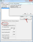
    The code for both of these actually sends the entire message over the XBee serial connection letter by letter. We built it this way since we were planning on sending typed messages). The code for each device is quite similar since this is a conversation and each is displaying to an LCD screen; the only difference is in the content of each message sent and that the device inside has a buzzer to indicate when somebody is at the door.

    Here is the arduino code for each:

    Internal/dominant

    External/abusee

     
  • Unknown's avatar

    Yury Gitman 4:02 am on March 1, 2011 Permalink | Reply  

    Must See Link. Wireless Sensor Networks and Emotive Robotics from PLAYSKOOL and Sesame Street. 

    http://www.toybook.com/TOY_2-11.html

     
c
Compose new post
j
Next post/Next comment
k
Previous post/Previous comment
r
Reply
e
Edit
o
Show/Hide comments
t
Go to top
l
Go to login
h
Show/Hide help
shift + esc
Cancel